Air-conditioner internal unit and air conditioner

An air conditioner internal unit and cyclone technology, applied in the field of air conditioners, can solve the problems of low working pressure, difficult to reduce the size of commercial air conditioners, and use occasions where limited installation space is required, so as to achieve compact installation space and small installation space. Effect

Pending Publication Date: 2017-12-29
GREE ELECTRIC APPLIANCES INC OF ZHUHAI
0 Cites 21 Cited by

AI-Extracted Technical Summary

Problems solved by technology

Many air-conditioning internal units of existing commercial air conditioners include centrifugal fans, motors, heat exchangers and other components. Because the direction of air intake and exhaust direction of centrifugal fans are perpendicular to each other, the size of commercial air conditioners is limited by this feature. It is difficult to reduce, and there are many restrictions on the installation position and direction of the centrifugal fan in th...

Method used

In Fig. 1, heat exchanger 3 is optionally arranged on the inner side relative to air inlet 12 in internal air passage 11, so that heat exchange is performed more comprehensively at the air intake position, compared to other positions The temperature difference between the airflow at the exhaust port and the outside can be reduced to reduce or eliminate condensation at the exhaust port. Specifically, it is preferable to install the heat exchanger 3 below the counter-cyclone fan 2 . In addition, a water receiving tray 4 may also be provided under the heat exchanger 3 so as to receive converging water droplets when dew condenses on the heat exchanger 3 to avoid polluting or corroding the body 1 .
The pair of cyclonic fans 2 can optionally include the first axial flow fan 21 and the second axial flow fan 22, the first axial flow fan 21 and the second axial flow fan 22 are arranged axially adjacent, and the first axial flow fan 21 and the second axial flow fan 22 in the opposite direction of rotation. That is, if the first axial fan 21 rotates clockwise, the second axial fan 22 rotates counterclockwise; or the first axial fan 21 rotates counterclockwise, then the second axial fan 22 rotates clockwise. More than one set of counter-rotating fans 2 can be arranged in the internal air duct 11. Two axial flow fans with opposite rotation directions can solve the problem that the static pressure of a single axial flow fan is small, and compared with the centrifugal fan, its installation direction And the location is less restricted, and the design is more free.
[0026] In order to facilitate the fixing of the output shaft of the outer rotor motor, a relatively fixed support with the inner air duct 11 can be set in the inne...

Abstract

The invention relates to an air conditioner inner unit and an air conditioner. The air conditioner inner unit includes: an internal air duct (11) and a counter-rotating fan (2), the inner air duct (11) and the air inlet of the air conditioner inner unit ( 12) is in communication with the exhaust port (13), and the counter-cyclone fan (2) is arranged in the internal air passage (11) for guiding the airflow from the air inlet (12) along the internal air passage (11) flows to said exhaust port (13). In the present invention, a counter-rotating fan is installed in the internal air duct of the air conditioner to guide the air flow. Compared with the existing scheme of using a centrifugal fan or a larger-sized axial fan to meet the air supply requirements, the counter-rotating fan used in the present invention can Under the condition of meeting the same air supply demand, the occupied installation space is smaller, which can meet the installation requirements of more applicable occasions, especially the occasions with relatively compact installation space requirements.

Application Domain

Technology Topic

AirflowSpace requirements +4

Image

  • Air-conditioner internal unit and air conditioner
  • Air-conditioner internal unit and air conditioner
  • Air-conditioner internal unit and air conditioner

Examples

  • Experimental program(1)

Example Embodiment

[0020] The technical solutions of the present invention will be further described in detail below through the accompanying drawings and embodiments.
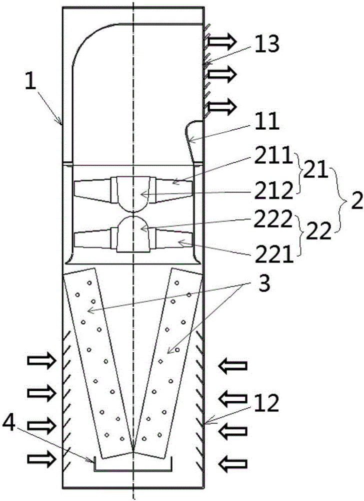
[0021] Such as figure 1 Shown is a schematic structural diagram of an embodiment of the internal air conditioner of the present invention. In this embodiment, the internal air conditioner includes: an internal air duct 11 and a counter-rotating fan 2. The internal air duct 11 is in communication with the air inlet 12 and the air outlet 13 of the internal air conditioner, and the counter-rotating fan 2 is arranged in the internal air duct 11 for guiding airflow from the air inlet 12 to the air outlet along the internal air duct 11 13.
[0022] The internal air duct 11 can be formed inside the body 1 of the air conditioner internal unit, and the air inlet 12 and the air outlet 13 can be referred to figure 1 It is shown at both ends of the internal air duct 11 respectively. In another embodiment, the positions of the air inlet 12 and the air outlet 13 may also be arranged at other positions of the internal air duct 11 except for the end. Internal air duct 11 can refer to figure 1 It is shown to be arranged in the vertical direction, and the air inlet 12 is arranged at the lower position of the body 1 and the air outlet 13 is arranged at the upper position of the body 1. In other embodiments, an internal air duct in a horizontal direction or an oblique direction may also be used, and the air inlet and the air outlet may also be arranged at other positions relative to the body 1.
[0023] The counter-rotating fan 2 may optionally include a first axial flow fan 21 and a second axial flow fan 22. The first axial flow fan 21 and the second axial flow fan 22 are arranged adjacent to each other in the axial direction, and the first axial flow fan 21 and the second axial flow fan 21 The rotation direction of the two axial flow fans 22 is opposite. That is, if the first axial fan 21 rotates clockwise, the second axial fan 22 rotates counterclockwise; it can also be that the first axial fan 21 rotates counterclockwise, and the second axial fan 22 rotates clockwise. More than one set of counter-rotating fans 2 can be arranged in the internal air duct 11. Two axial fans with opposite rotations can solve the problem of a single axial fan with a smaller static pressure, and compared to centrifugal fans, the installation direction There are fewer restrictions on and location, and more freedom in design.
[0024] reference figure 1 with figure 2 , The first axial fan 21 may include an axial fan 211 and a motor 212, and the second axial fan 22 may include an axial fan 221 and a motor 222. The motors 212 and 222 are independent of each other and adjacent in space. The motor output shafts of the motors 212 and 222 can extend in opposite directions to the same axis. The axial fan blades 211 and 221 can be installed on the output shaft of the motor, or can be installed on the motor housing.
[0025] In one embodiment, reference image 3 , The axial flow blades 2a in the first axial flow fan 21 and the second axial flow fan 22 both use external rotor motors to provide driving force, that is to say, the motors 212 and 222 are both external rotor motors. The inner ring 2b of the axial flow fan 2a is fixedly arranged, and the output shaft of the outer rotor motor is fixed relative to the inner air duct 11. In another embodiment, any one of the first axial flow fan 21 and the second axial flow fan 22 may be an outer rotor motor, and the other may be an inner rotor motor.
[0026] In order to facilitate the fixing of the output shaft of the outer rotor motor, a bracket relatively fixed to the inner air channel 11 may be provided in the inner air duct 11, and the output shaft of the outer rotor motor is fixed to the bracket. For example, a cross-shaped bracket is provided in the internal air duct 11, and the center of the bracket is fixed to the output shaft of the outer rotor motor. Because the output shaft of this kind of outer rotor motor is fixed, the inner ring 2b of the axial flow fan 2a is fixed to the outer rotor motor shell, so the cantilever length of the corresponding axial flow fan is 1/2 the length of the shell + the length of the output shaft. The rotor motor has a shorter cantilever length (equal to the length of the housing + the length of the output shaft), so the bending load is lower.
[0027] reference figure 2 The numbers of the axial flow blades of the first axial flow fan 21 and the axial flow blades of the second axial flow fan 22 are preferably mutually prime to eliminate the resonance phenomenon that may occur during operation. For example, the axial flow blade 211 includes 6 blades, and the axial flow blade 221 includes 7 blades. In addition, the positions of the first axial flow fan 21 and the second axial flow fan 22 can be exchanged with respect to the direction of air movement, and the blade angle and rotation direction can be adjusted accordingly according to specific conditions.
[0028] If the above-mentioned embodiment of the air conditioner internal machine using the counter-rotating fan 2 and the air conditioner internal machine using a single axial fan are used in the same design air volume (for example, 1200m 3 /h) and rotating speed (N=960rad/min), the outer diameter of the counter-rotating fan in the embodiment of the air conditioner of the present invention is about 20% smaller than that of a single axial fan. The static pressure increases by 18%, and the efficiency increases by 10%.
[0029] In order to further reduce the installation space of the internal air conditioner, refer to figure 1 The embodiment of the internal air conditioner of the present invention may further include a heat exchanger 3 arranged in the internal air duct 11 in a V-shaped layout. Compared with the existing in-line heat exchanger, the heat exchange area of ​​this V-shaped layout heat exchanger is nearly doubled, and the layout space in the body 1 is not significantly increased.
[0030] in figure 1 , The heat exchanger 3 can be optionally arranged on the inner side of the internal air duct 11 relative to the air inlet 12, so that heat exchange can be carried out more comprehensively at the air inlet position, and the airflow at the air outlet can be reduced compared to other positions The temperature difference with the outside world to reduce or eliminate condensation at the exhaust outlet. Specifically, it is preferable to install the heat exchanger 3 below the counter-rotating fan 2. In addition, a water-receiving pan 4 can also be provided under the heat exchanger 3 so as to receive the water droplets from the confluence when the heat exchanger 3 is condensed to avoid pollution or corrosion of the body 1.
[0031] The aforementioned internal air conditioners can be applied to various types of air conditioning equipment, and are especially suitable for air conditioners. Therefore, the present invention also provides an air conditioner, including the aforementioned internal air conditioner, which can achieve the technical effect of reducing the installation space occupation.
[0032] Finally, it should be noted that the above embodiments are only used to illustrate the technical solutions of the present invention and not to limit it; although the present invention has been described in detail with reference to the preferred embodiments, those of ordinary skill in the art should understand that: The specific implementation of the invention is modified or some technical features are equivalently replaced; without departing from the spirit of the technical solution of the invention, all of them shall be covered by the scope of the technical solution claimed by the invention.

PUM

no PUM

Description & Claims & Application Information

We can also present the details of the Description, Claims and Application information to help users get a comprehensive understanding of the technical details of the patent, such as background art, summary of invention, brief description of drawings, description of embodiments, and other original content. On the other hand, users can also determine the specific scope of protection of the technology through the list of claims; as well as understand the changes in the life cycle of the technology with the presentation of the patent timeline. Login to view more.

Similar technology patents

Traditional Chinese medicine decoction device

ActiveCN105287216AReduces the risk of inconsistent decoction quality or drug mix-upsSave installation spacePharmaceutical product form changeDomestic articlesMedicinal herbsEngineering
Owner:永春县产品质量检验所福建省香产品质量检验中心国家燃香类产品质量监督检验中心福建

Emergency rescue vehicle

PendingCN107653920ARealize collaborative workSave installation spaceMechanical machines/dredgersEndless track vehiclesEngineeringEmergency rescue
Owner:JIANGSU XCMG CONSTR MASCH RES INST LTD

Classification and recommendation of technical efficacy words

  • Compact installation space
  • Save installation space

Rotary filter screen, filter screen assembly and range hood

ActiveCN110500628ACompact installation spaceCompact installationDomestic stoves or rangesLighting and heating apparatusKitchen utensilsEngineering
Owner:FOSHAN SHUNDE MIDEA WASHING APPLIANCES MFG

Rotary filter screen, filter screen assembly and range hood

ActiveCN110500627ACompact installation spaceCompact installationDomestic stoves or rangesLighting and heating apparatusKitchen utensilsEngineering
Owner:FOSHAN SHUNDE MIDEA WASHING APPLIANCES MFG

Delivering and bag conveying device of vertical packaging machine

InactiveCN106428789ACompact installation spaceReasonable structural designPackagingEngineeringAutomation
Owner:HEFEI SANGUAN PACKING SCI & TECH

Heating and hot water supply device

ActiveUS20190154304A1Increase in sizeCompact installation spaceCentral heating componentsWater heatersEngineeringCirculating pump
Owner:NORITZ CORP
Why Eureka
Try Eureka