Supercharge Your Innovation With Domain-Expert AI Agents!

Heat pump drying device

A drying device and heat pump technology, applied in the field of drying, can solve problems such as energy waste

Active Publication Date: 2020-08-07
ZHEJIANG SANHUA INTELLIGENT CONTROLS CO LTD
View PDF6 Cites 0 Cited by
  • Summary
  • Abstract
  • Description
  • Claims
  • Application Information

AI Technical Summary

Problems solved by technology

[0005] As the drying process proceeds, the moisture content of the load in the drying chamber 5' gradually decreases, and the heat load required by the load also gradually decreases. In order to ensure the energy efficiency of the system and the safety and reliability of the work, an auxiliary fan 6' is generally installed to Exclude the redundant load of the compressor 1'; at present, about 40% of the electric power input by the compressor 1' is dissipated in the form of heat energy, resulting in a large amount of energy waste

Method used


Image

  • Heat pump drying device
  • Heat pump drying device
  • Heat pump drying device

Examples


Embodiment Construction

[0033] In order to enable those skilled in the art to better understand the solution of the present invention, the present invention will be further described in detail below in conjunction with the accompanying drawings and specific embodiments.

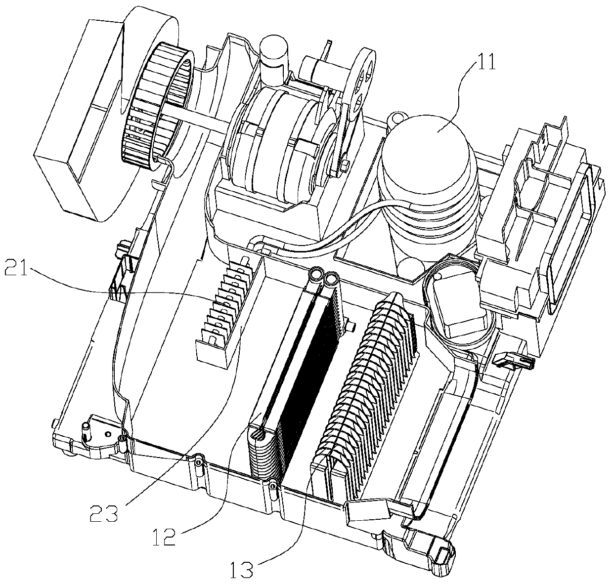
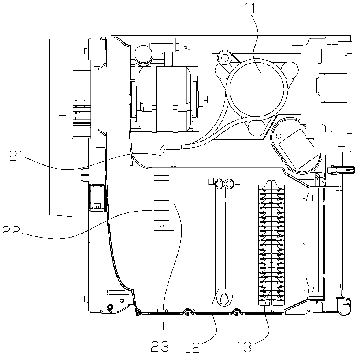
[0034] Please refer to Figure 2 to Figure 4 , figure 2 It is a structural schematic diagram of a specific embodiment of the heat pump drying device provided by the present invention; image 3 for figure 2 top view of Figure 4 for figure 2 Schematic diagram of the principle of the heat pump drying device shown.

[0035] The heat pump drying device includes a compressor 11 , a condenser 12 , an evaporator 13 , a throttling element 14 , a drying chamber 15 and a closed-loop air duct 16 .

[0036] Among them, the condenser 12, the evaporator 13 and the drying chamber 16 are all placed in the closed-loop air duct 16, and the wind field of the closed-loop system is established by the fan, and the air driven by the fan flows thro...


PUM


Abstract

The invention discloses a heat pump type drying device which comprises a compressor, a condenser, an evaporator and a drying chamber. The condenser, the evaporator and the drying chamber are arranged in a closed-loop air way. Air in the closed-loop air way can sequentially flow through the evaporator, the condenser and the drying chamber to form closed circulation. The heat pump drying device further comprises a heat pipe, an evaporation section of the heat pipe is connected with the outer wall of the compressor in a heat conduction manner, and a condensation section of the heat pipe is located in the closed-loop air way. By means of the heat pump type drying device, waste heat of the compressor can be transmitted to the closed-loop air way, heat input of the system is increased, meanwhile, overheat of the compressor can be prevented, it is ensured that the exhaust temperature and pressure of the compressor are stable, and stability of the working condition of the system is maintained.

Description

technical field [0001] The invention relates to the technical field of drying, in particular to a heat pump drying device. Background technique [0002] Please refer to figure 1 , figure 1 It is a schematic diagram of the principle of an existing heat pump drying device. [0003] Generally, a heat pump drying device has an air circulation circuit and a refrigerant circulation circuit, wherein the air circulation circuit includes a drying chamber 5', a fan, a condenser 2' and an evaporator 3', and these four components are placed in a closed air duct , the fan drives the air circulation to establish the wind field of the closed-loop system. The hollow arrow in the figure shows the flow path of the air; the refrigerant circulation circuit includes a compressor 1', a condenser 2', an evaporator 3' and a throttling Element 4'. [0004] When working, first start the fan to establish the wind field of the closed-loop system, then start the compressor 1', the heat pump system w...

Claims


Application Information

Patent Timeline
Patent Type & Authority Patents(China)
IPC IPC(8): F26B9/06F26B21/02F26B23/00D06F58/20
CPCD06F58/206F26B9/06F26B21/02F26B23/008Y02P70/10
Inventor 王一鸣张森铼
Owner ZHEJIANG SANHUA INTELLIGENT CONTROLS CO LTD
Features
  • R&D
  • Intellectual Property
  • Life Sciences
  • Materials
  • Tech Scout
  • Unparalleled Data Quality
  • Higher Quality Content
  • 60% Fewer Hallucinations
Learn More