
A photovoltaic power generation control method and photovoltaic power generation system

A technology of photovoltaic power generation system and control method, which is applied in the field of photovoltaic power generation control and photovoltaic power generation system, and can solve problems such as photovoltaic energy loss

Active Publication Date: 2020-09-25
HUAWEI DIGITAL POWER TECH CO LTD
View PDF3 Cites 0 Cited by
  • Summary
  • Abstract
  • Description
  • Claims
  • Application Information

AI Technical Summary

Problems solved by technology

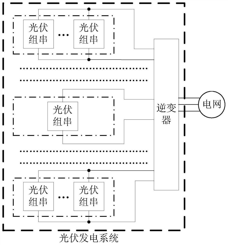
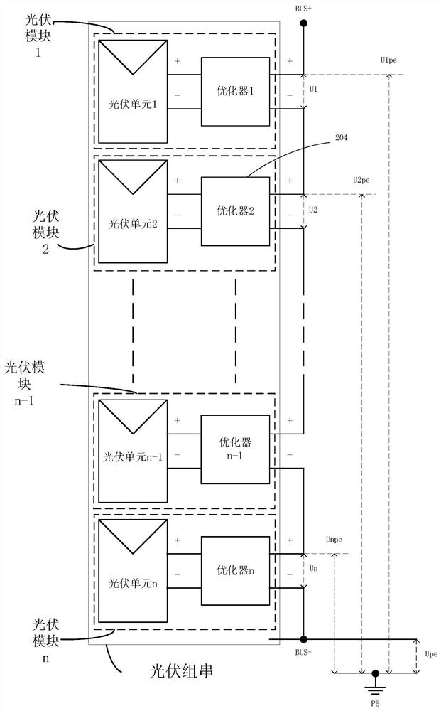
[0004] In the existing guarantee measures, the upper limit of the BUS voltage is set for the PV string. Since the optimizers in a single PV string are connected in series, the BUS voltage is equivalent to the sum of the output voltages of each optimizer. Therefore, each The sum of the upper limit of the output voltage of the optimizer is equivalent to the upper limit of the BUS voltage. In other words, the voltage margin between the normal operating voltage of each optimizer and the upper limit of the output voltage is as small as 5V, and when the BUS voltage When the upper limit is the same, as the number of optimizers increases, the above voltage margin value of each optimizer will also decrease. When the photovoltaic module corresponding to the optimizer is shaded, due to the voltage margin of each optimizer If the output voltage is small, the output voltage of some optimizers will reach the upper limit of the output voltage, making this part of the optimizer work in a power-limited state, resulting in the loss of photovoltaic energy. At this time, the photovoltaic power generation system needs to increase the upper limit of the output voltage of the optimizer. , so that the converter exits the power-limited state and enters the MPPT state to work

Method used


Image

  • A photovoltaic power generation control method and photovoltaic power generation system
  • A photovoltaic power generation control method and photovoltaic power generation system
  • A photovoltaic power generation control method and photovoltaic power generation system

Examples


Embodiment Construction

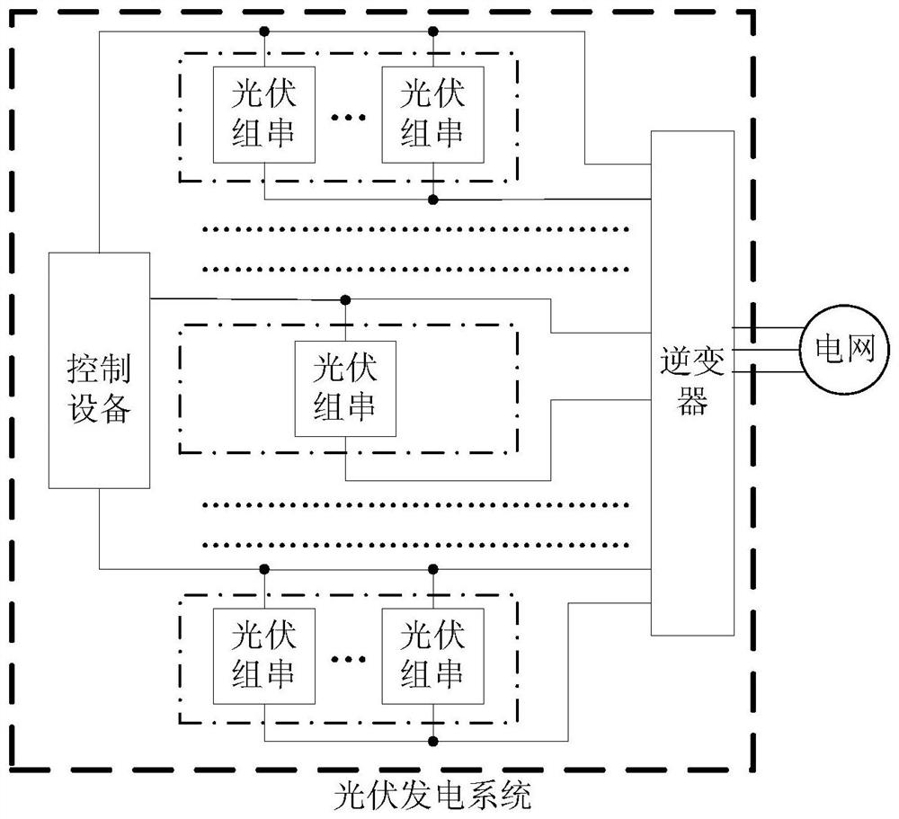
[0029] Embodiments of the present application provide a photovoltaic power generation control method and a photovoltaic power generation system, which are used to reduce photovoltaic energy loss of the photovoltaic power generation system.

[0030] The terms "first", "second", "third", "fourth", etc. (if any) in the specification and claims of the present application and the above drawings are used to distinguish similar objects, and not necessarily Used to describe a specific sequence or sequence. It is to be understood that the terms so used are interchangeable under appropriate circumstances such that the embodiments described herein can be practiced in sequences other than those illustrated or described herein. Furthermore, the terms "comprising" and "having", as well as any variations thereof, are intended to cover a non-exclusive inclusion, for example, a process, method, system, product or device comprising a sequence of steps or elements is not necessarily limited to t...


PUM


Abstract

The embodiment of the present application discloses a control method of a photovoltaic power generation system and a photovoltaic power generation system, which are used to reduce photovoltaic energy loss of the photovoltaic power generation system. The method in the embodiment of the present application includes: the photovoltaic power generation system presets an upper limit value for each converter in the photovoltaic power generation system, and the upper limit value is the maximum voltage value of the output voltage of the converter to ground, so The output-to-ground voltage is the voltage difference between the positive output terminal of the converter and the ground point of the photovoltaic power generation system; the photovoltaic power generation system limits the output of the target converter to ground voltage, and the target converter is any converter in the photovoltaic power generation system.

Description

technical field [0001] The present application relates to the field of photovoltaic power generation, in particular to a photovoltaic power generation control method and a photovoltaic power generation system. Background technique [0002] In a photovoltaic power generation system using optimizers and distributed maximum power point tracking (MPPT) technology, in order to ensure that the photovoltaic power generation system can work normally in any scenario, measures need to be taken to ensure that each optimization in the photovoltaic power generation system The sum of the output voltages of the devices (referred to as the BUS voltage) is always lower than the system voltage. When the output voltage of the optimizer is less than the upper limit of the output voltage, the optimizer works in the MPPT state without photovoltaic energy loss; when the output voltage of the optimizer is greater than or equal to the upper limit of the output voltage, the optimizer works in the sta...

Claims


Application Information

Patent Timeline
Patent Type & Authority Patents(China)
IPC IPC(8): H02J3/38H02S40/32H02S40/30
CPCH02J3/385H02S40/30H02S40/32Y02E10/56H02J2300/26H02J3/381G05F1/67
Inventor 高拥兵顾桂磊
Owner HUAWEI DIGITAL POWER TECH CO LTD
Learn More