Positioning structure of miniature metal sheet in injection mold

A positioning structure and metal sheet technology, applied in the direction of coating, etc., can solve the problems of large size, increased cost, and easy falling off of steel sheets, and achieve the effects of reducing mold repair costs, improving production efficiency, and saving cutting processes

Active Publication Date: 2018-01-05
深圳市欧骏模具科技有限公司
View PDF4 Cites 0 Cited by
  • Summary
  • Abstract
  • Description
  • Claims
  • Application Information

AI Technical Summary

Problems solved by technology

Because the steel sheet is too small, it cannot be fixed well, and the steel sheet is easy to fall off during production, which causes the mold
[0003] Invention (Authorization Notice No. CN 206426386U): A small metal sheet fixing device in an injection mold. A solution announced: including a fixing plate, a pressing plate and a buckle. There are chutes on both sides of the top of the fixing plate. The fixed plate is connected; there is a buckle under the pressure plate, and the buckle and the direction of the pressure plate are matched in the same direction; the side of the pressure plate facing the buckle is provided with a positioning needle sleeve, and the side of the buckle facing the pressure plate is provided with a positioning pin corresponding to the positioning needle sleeve. There is a thimble on the bottom of the buckle; this method can indeed fix and maintain small metal pieces, but its size is too large, and it is used on the mold, the mold design will be very complicated, and the cost will be increased

Method used


Image

  • Positioning structure of miniature metal sheet in injection mold
  • Positioning structure of miniature metal sheet in injection mold
  • Positioning structure of miniature metal sheet in injection mold

Examples


Embodiment Construction

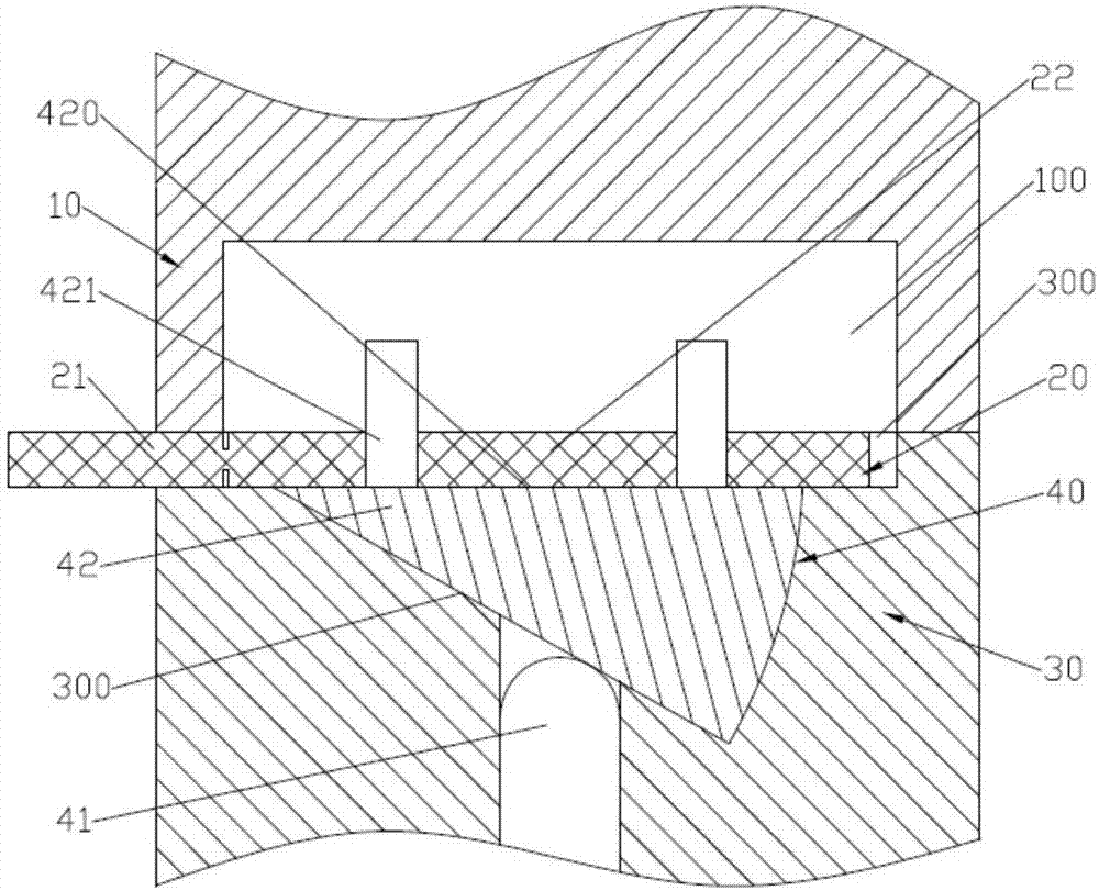
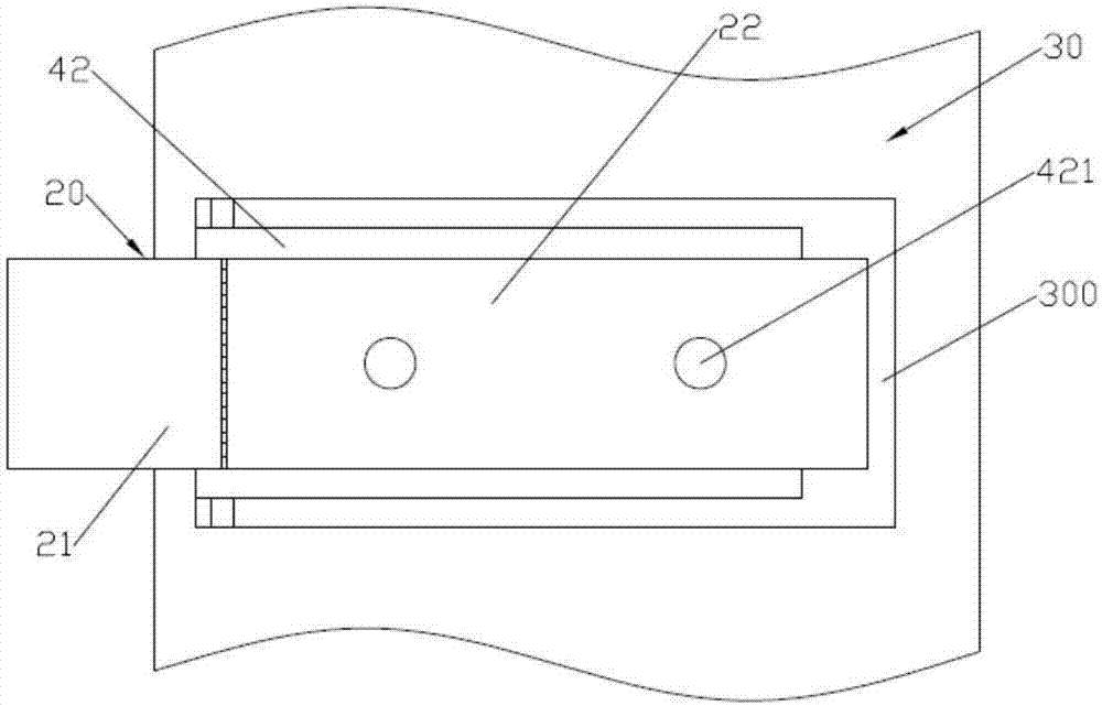
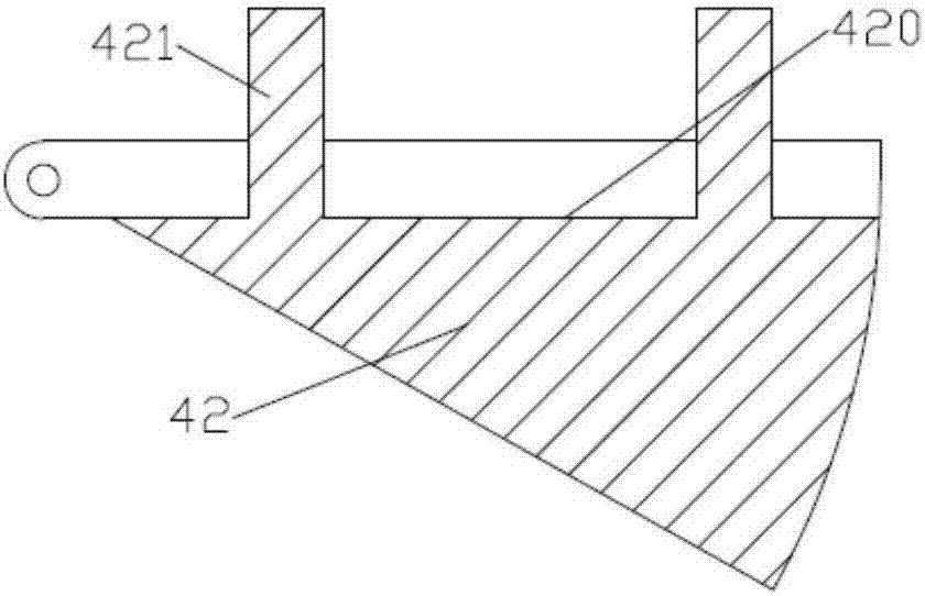
[0015] like Figure 1 ~ Figure 3 As shown, a positioning structure for small metal sheets in an injection mold includes an upper mold 10, a metal sheet unit 20, a lower mold 30 and a supporting breaking device 40; the lower end surface of the side wall of the upper mold 10 is formed with a rectangular breaking groove 100 The sheet metal unit 20 is made up of the sheet metal body 21 on the left and the supporting sheet 22 on the right; The end surface is formed with a placement groove 300 that runs through the left side; the supporting breaking device 40 includes a rotating breaking block 42; the left end of the rotating breaking block 42 is hinged between the front and rear side walls of the placement groove 300; the upper end surface of the rotating breaking block 42 is formed with left and right through The limit groove 420; when the upper end surface of the rotating breaking block 42 is in a horizontal state, the bottom surface of the limit groove 420 is flush with the bott...


PUM


Abstract

The invention discloses a positioning structure of a miniature metal sheet in an injection mold. The positioning structure comprises an upper mold, a metal sheet unit, a lower mold and a support breaking device, wherein a rectangular breaking groove is formed at the lower end surface of the upper mold; the metal sheet unit consists of a left metal sheet body and a right support sheet; the metal sheet body and the support sheet are connected together by a plurality of front and back alternative connecting sheet sections; a left penetrated placing groove is formed at the upper end surface of theside wall of the lower mold; the support breaking device comprises a rotary breaking block; the left end of the rotary breaking block is hinged between the front side wall and back side wall of the placing groove; a limiting groove is formed at the upper end surface of the rotary breaking block; when the right end of the metal sheet unit is placed into the placing groove, the support sheet is positioned in the limiting groove, and the connecting sheet sections between the metal sheet body and the support sheet just face the left side wall of the breaking groove. The positioning structure hasthe advantages that the structure is simple; the problems of difficulty in positioning and easiness in falling of the miniature metal sheet in the mold are solved; the pressing to the mold is avoided,and the mold repair cost is reduced.

Description

technical field [0001] The invention relates to the technical field of injection molds, in particular to a positioning structure for small metal sheets in an injection mold. Background technique [0002] It has always been a difficult problem to locate and fix small steel sheets in the mold with dimensions within 25*15*0.2. Because the steel sheet is too small, it cannot be fixed well, and the steel sheet is easy to fall off during production, resulting in compression molding. [0003] Invention (Authorization Notice No. CN 206426386U): A small metal sheet fixing device in an injection mold. A solution announced: including a fixing plate, a pressing plate and a buckle. There are chutes on both sides of the top of the fixing plate. The fixed plate is connected; there is a buckle under the pressure plate, and the buckle and the direction of the pressure plate are matched in the same direction; the side of the pressure plate facing the buckle is provided with a positioning nee...

Claims


Application Information

Patent Timeline
Patent Type & Authority Applications(China)
IPC IPC(8): B29C45/14B29C45/26
Inventor 杨勇
Owner 深圳市欧骏模具科技有限公司
Why Eureka
Try Eureka