A tailgate catenary transport device

A technology of transportation device and tailgate, which is applied in transportation and packaging, conveyors, mechanical conveyors, etc., can solve the problem of high logistics cost, and achieve the effect of reducing unqualified products, improving transportation efficiency and reducing transportation costs.

Active Publication Date: 2019-01-04
东风彼欧(成都)汽车外饰系统有限公司
View PDF7 Cites 0 Cited by
  • Summary
  • Abstract
  • Description
  • Claims
  • Application Information

AI Technical Summary

Problems solved by technology

[0002] At present, in the automotive industry, the supply of parts suppliers is generally transported by truck to the warehouse of the main engine factory, and then transferred to the logistics form of the assembly line, and the logistics cost is high.

Method used


Image

  • A tailgate catenary transport device
  • A tailgate catenary transport device
  • A tailgate catenary transport device

Examples


Embodiment 1

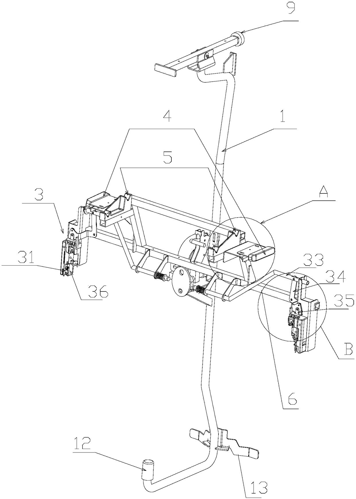
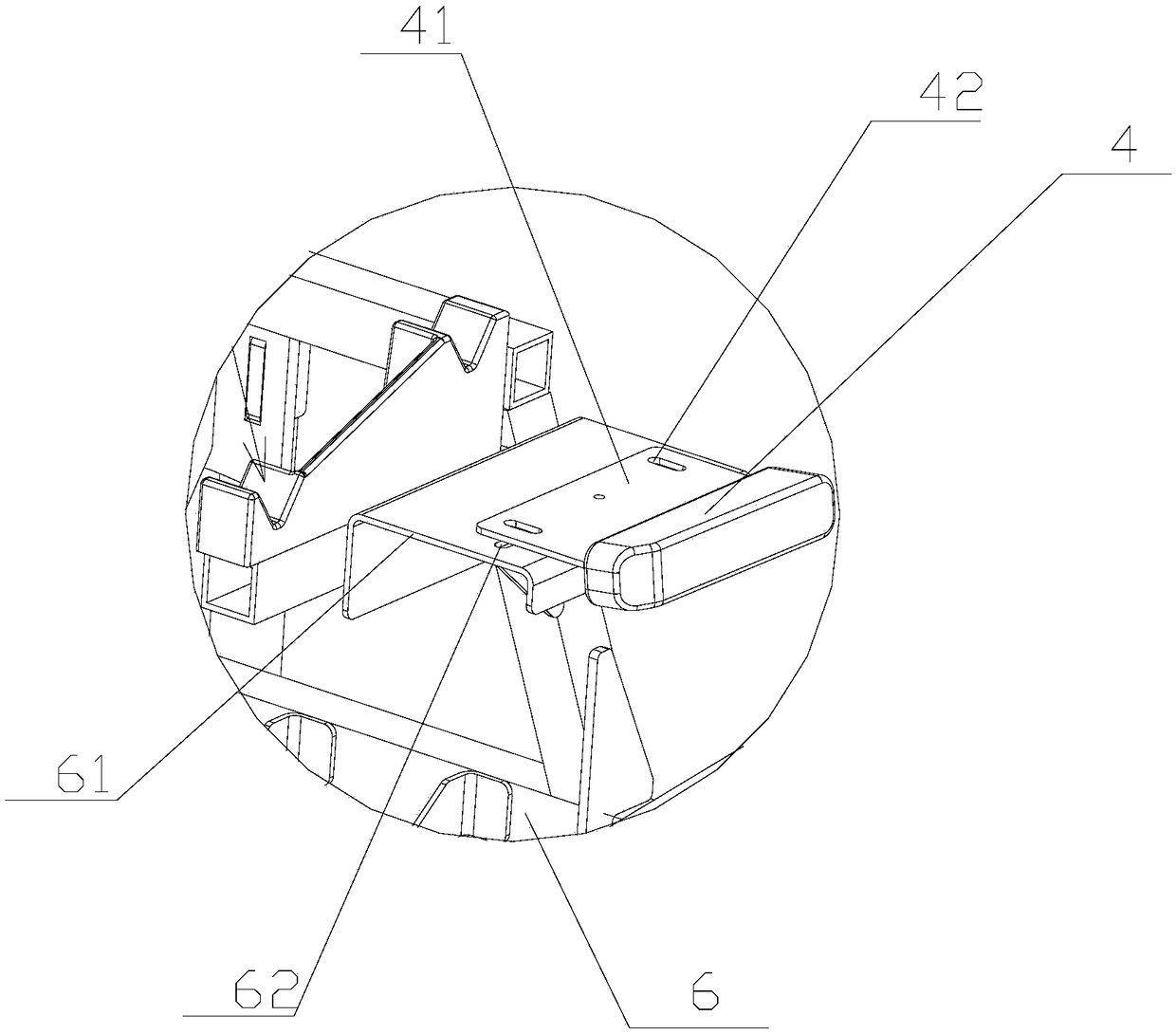
[0033] Such as figure 1 As shown, the tailgate catenary transportation device disclosed in this embodiment includes a support rod 1 and a tailgate fixing device 2 , the tailgate fixing device 2 is installed on the support rod 1 , and the support rod 1 is located in the middle of the tailgate fixing device 2 . The tailgate fixing device 2 includes a bracket 6, a locking device 3, a fixing slot 5 and a limiting device for limiting the left and right movement of the tailgate. The locking device 3, the limiting device and the fixing slot 5 are all installed on the bracket 6 . The limiting device includes a limiting block 4, and there are two locking devices 3 and two limiting blocks 4. The two locking devices 3 are respectively arranged on the left and right sides of the bracket 6, and the two limiting blocks 4 are also respectively arranged on the bracket 6. On the left and right sides, the fixed card slot 5 is located inside the two limit blocks 4, and the fixed card slot 5 ope...

Embodiment 2

[0040] The difference between this embodiment and embodiment 1 is: as Figure 7 As shown, the tailgate fixing device 2 is installed on the support bar 1 through the bearing 7 and the limit pin 8, and the rotating shaft 64 fixedly connected with the bracket 6 is installed on the bearing 7. The support bar 1 is provided with a fan-shaped plate 11, and the fan-shaped plate 11 There are two limiting grooves 10 adapted to the limiting pin 8, and the two limiting grooves 10 are arranged around the rotating shaft 64. The angle between the centerlines of the two limiting grooves 10 is 90 degrees. Such as Figure 7 As shown, one of the limiting grooves 10 is located directly above the rotating shaft 64 .

[0041] During use, the top pulley 9 is connected with the catenary, and the two ends of the catenary are respectively the supplier's loading area and the corresponding product assembly station of the main engine factory. In the initial state, such as Figure 8As shown, the stop pi...

Embodiment 3

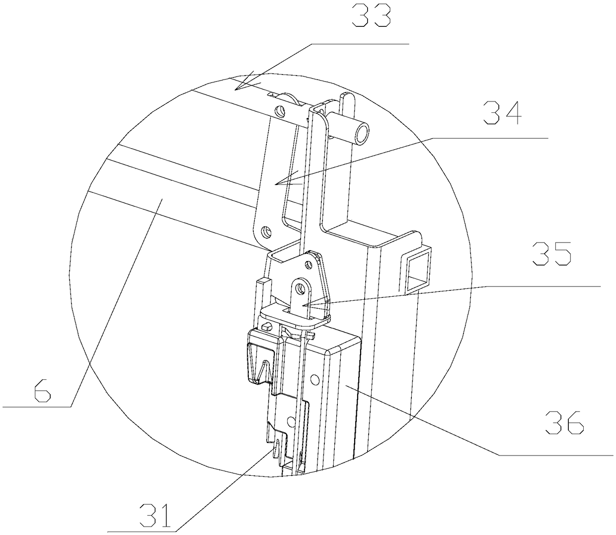
[0043] The difference between this embodiment and embodiment 1 or 2 is: as Figure 10 As shown, the adjusting rod 33 is installed on the support 6 by the mounting arm 63, the mounting arm 63 is fixedly connected with the support 6, the adjusting rod 33 cooperates with the through hole clearance on the mounting arm 63, the adjusting rod 33 is provided with a spring 37, and the adjusting rod 33 is provided with a spring 37. And compress the spring 37 to realize the horizontal movement of the adjusting rod 33.


PUM


Abstract

The invention relates to a tail door suspension chain transport device which comprises a supporting rod and a tail door fixing device. The tail door fixing device is mounted on the supporting rod. Thesupporting rod is located in the middle of the tail door fixing device. A pulley is arranged at the top of the supporting rod. The tail door fixing device comprises locking devices, fixed clamp grooves, a limiting device used for limiting left-and-right movement of a tail door and a support, and the locking devices, the limiting device and the fixed clamp grooves are all mounted on the support. The limiting device comprises limiting blocks. Each locking device comprises at least one tongue piece and an adjusting mechanism used for adjusting the up-and-down position of the tongue piece. A ballhead pin clamp groove is formed in each tongue piece. The tail door fixing device is mounted on the supporting rod through a bearing and a limiting pin. According to the tail door suspension chain transport device, the transport efficiency can be improved, and the transport cost can be reduced; and flexible transport is achieved, and the situation that products are unqualified due to the reasonssuch as colliding generated in the transport process is reduced.

Description

technical field [0001] The invention relates to the technical field of catenary transportation devices, in particular to a tailgate catenary transportation device. Background technique [0002] At present, in the automotive industry, the supply of parts suppliers is generally transported by truck to the warehouse of the main engine factory, and then transferred to the logistics form of the assembly line, and the logistics cost is high. In addition, with the popularity of the concept of just-in-time production, more and more OEMs require component suppliers to adopt just-in-time production systems and zero inventory management. Contents of the invention [0003] The invention aims to provide a tailgate catenary transport device, which can improve transport efficiency and reduce transport cost. [0004] In order to achieve the above object, the technical scheme adopted in the present invention is as follows: [0005] A tailgate catenary transport device, comprising a suppo...

Claims


Application Information

Patent Timeline
Patent Type & Authority Patents(China)
IPC IPC(8): B65G17/20B65G35/06
Inventor 蒲永太孙海明付洋
Owner 东风彼欧(成都)汽车外饰系统有限公司
Why Eureka
Try Eureka