
Natural gas pipeline monitoring system

A natural gas pipeline and monitoring system technology, applied in the field of natural gas pipeline monitoring, can solve the problems of inability to realize real-time monitoring of natural gas pipelines, stoppages, economic construction losses, etc.

Inactive Publication Date: 2018-01-05
缪建良
View PDF0 Cites 1 Cited by
  • Summary
  • Abstract
  • Description
  • Claims
  • Application Information

AI Technical Summary

Problems solved by technology

During the long-term operation of natural gas pipelines, cracks and trachoma occur due to their own material defects, rot occurs due to corrosion, cracks occur due to external damage, and gas leakage occurs due to gas theft, causing great losses to economic construction and extremely serious damage to safe operation. Great harm, causing great damage to the surrounding environment
However, the current monitoring of natural gas pipelines is still to check after the pipeline leaks, and it is impossible to realize real-time monitoring of natural gas pipelines, and there are potential safety hazards

Method used


Image

  • Natural gas pipeline monitoring system

Examples


Embodiment Construction

[0010] In order to facilitate the understanding of the present invention, the present invention will be described more fully below with reference to the associated drawings. Preferred embodiments of the invention are shown in the accompanying drawings. However, the present invention can be embodied in many different forms and is not limited to the embodiments described herein. On the contrary, the purpose of providing these embodiments is to make the disclosure of the present invention more thorough and comprehensive. It should be noted that when an element is considered to be "connected" to another element, it may be directly connected to the other element or there may be intervening elements at the same time. Unless otherwise defined, all technical and scientific terms used herein have the same meaning as commonly understood by one of ordinary skill in the technical field of the invention. The terms used herein in the description of the present invention are for the purpos...


PUM


Abstract

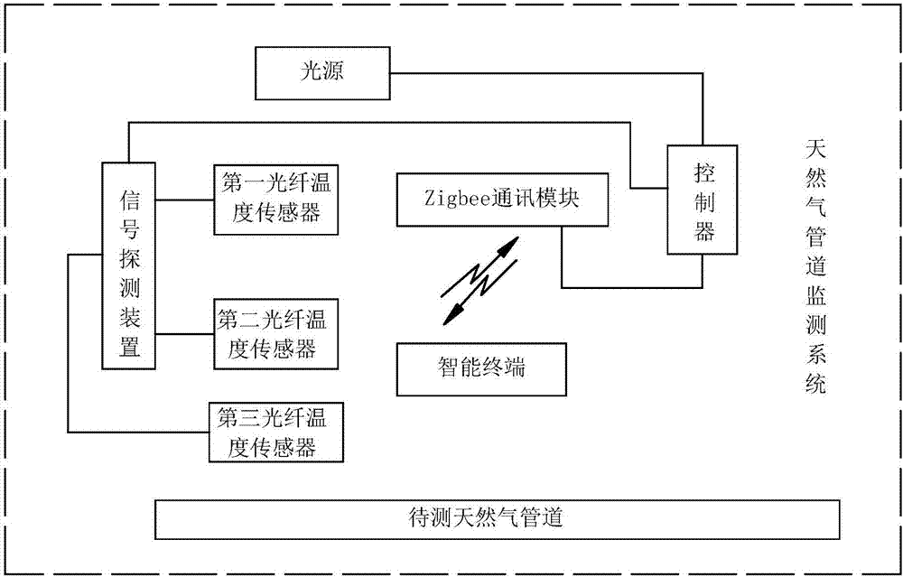
The invention discloses a natural gas pipeline monitoring system, comprising a light source, a first optical fiber temperature sensor, a second optical fiber temperature sensor, a third optical fiber temperature sensor, a signal detection device, a controller, a Zigbee communication module, and an intelligent terminal; the light source is connected and controlled The device is used to illuminate under the control of the controller; the first optical fiber temperature sensor, the second optical fiber temperature sensor, and the third optical fiber temperature sensor are all connected to the signal detection device; the signal detection device is connected to the controller, Zigbee communication module, intelligent Terminal: the first optical fiber temperature sensor, the second optical fiber temperature sensor, and the third optical fiber temperature sensor are arranged at intervals directly above the natural gas pipeline to be tested. In the present invention, the controller controls the light source to continuously illuminate the optical fiber temperature sensor, and obtains the temperature data of the natural gas pipeline in real time. The intelligent terminal analyzes the status of the natural gas pipeline according to the obtained temperature data, and judges whether leakage has occurred or is about to occur.

Description

technical field [0001] The invention relates to the field of natural gas pipeline monitoring, in particular to a natural gas pipeline monitoring system. Background technique [0002] Natural gas is a hazardous chemical, flammable and explosive. During the long-term operation of natural gas pipelines, cracks and trachoma occur due to their own material defects, rot occurs due to corrosion, cracks occur due to external damage, and gas leakage occurs due to gas theft, causing great losses to economic construction and extremely serious damage to safe operation. Great harm, causing great damage to the surrounding environment. However, the current monitoring of natural gas pipelines is still to check after the pipeline leaks, which cannot realize real-time monitoring of natural gas pipelines, and there are potential safety hazards. Contents of the invention [0003] The purpose of the present invention is to solve the problems mentioned in the background technology section abo...

Claims


Application Information

Patent Timeline
IPC IPC(8): F17D1/02F17D5/02
Inventor 缪建良
Owner 缪建良
Learn More