Elevator installations and storage media
An elevator and storage technology, applied in the directions of transportation, packaging, elevators, etc., can solve problems such as the limitation of the interval between detection boards
- Summary
- Abstract
- Description
- Claims
- Application Information
AI Technical Summary
Problems solved by technology
Method used
Image
Examples
no. 1 approach >
[0028] [Overall structure of the elevator device]
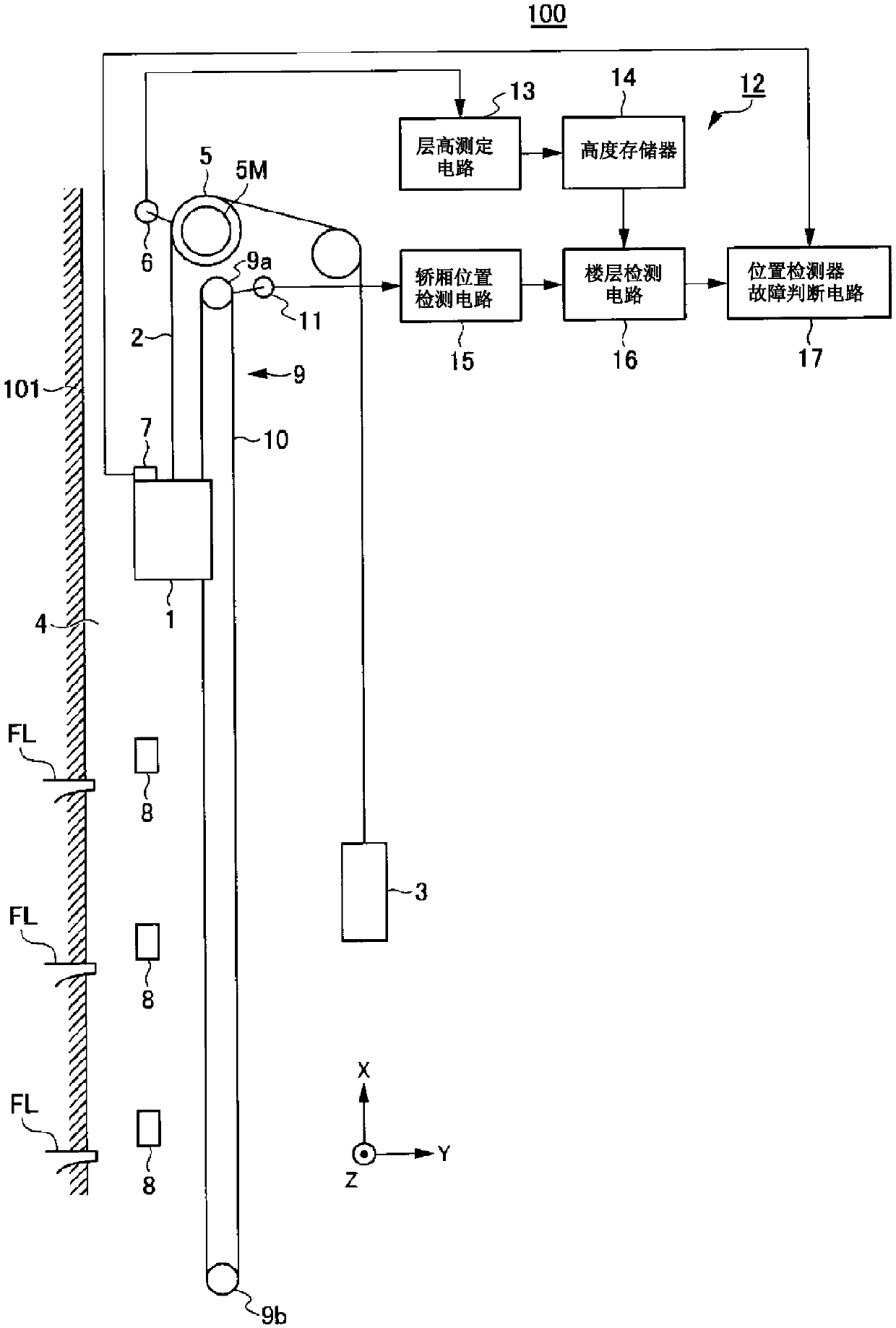
[0029] figure 1 It is a schematic diagram showing an example of the overall configuration of the elevator apparatus according to the first embodiment of the present invention. figure 1 In FIG. 2 , the structure of the module for detecting the failure of the position detector 7 for determining the position of the car 1 is also shown. figure 1 Herein, it is assumed that the lifting direction of the car 1 of the elevator device 100 is the X direction, the direction perpendicular to the X direction is the Y direction, and the direction perpendicular to the X direction and the Y direction is the Z direction.
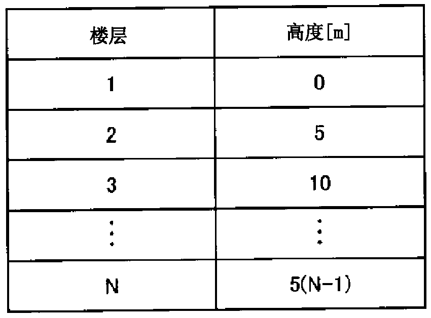
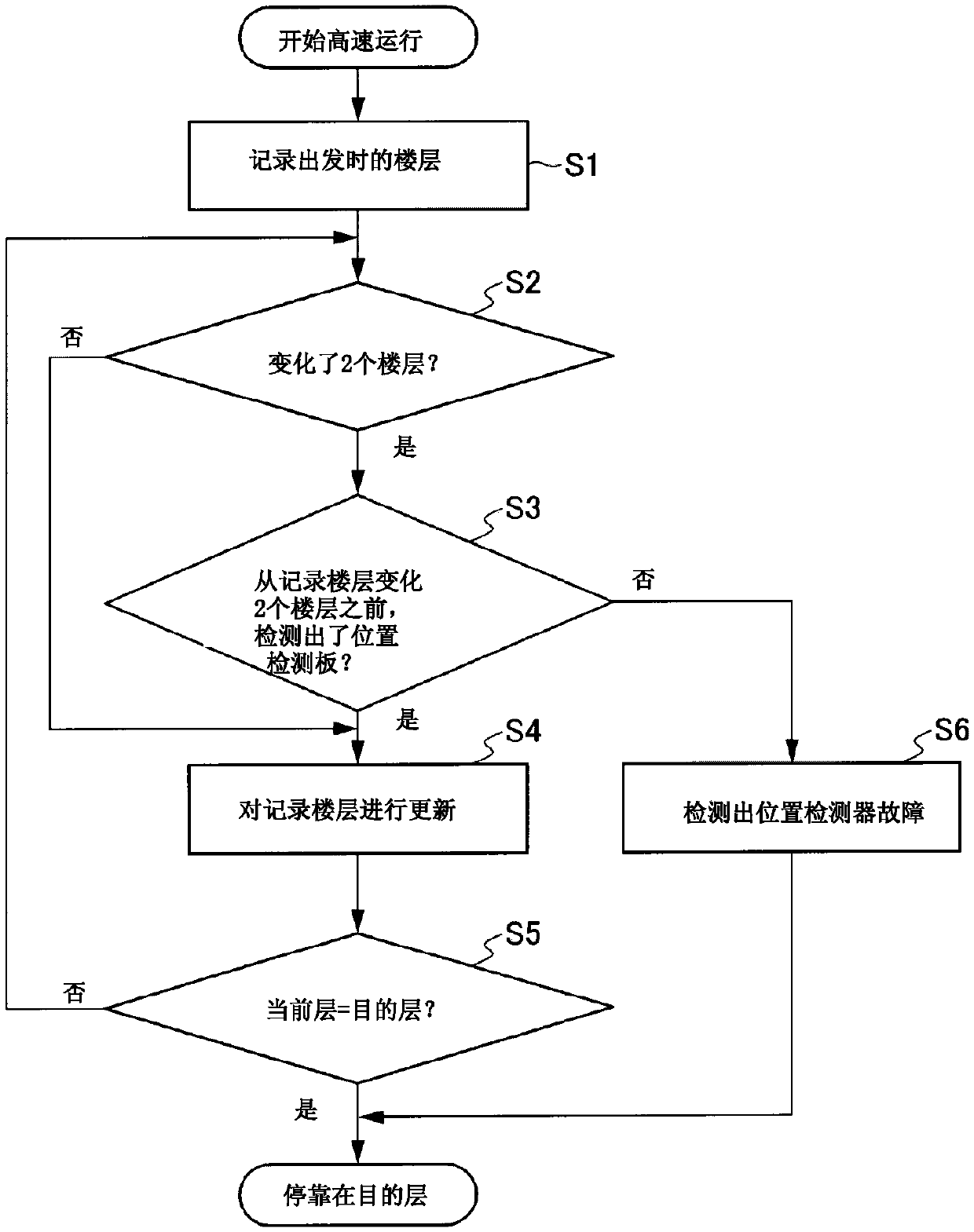
[0030] The elevator apparatus 100 is configured such that a car 1 (elevating body) is connected to a counterweight 3 via main ropes 2 in an elevator hoistway 4 provided in a building 101, and the car 1 can be raised and lowered along guide rails not shown. A machine room (not shown) is provided above the hoistway 4 (outsid...
no. 2 approach >
[0077] The second embodiment differs from the first embodiment in that the altimeter of the altimeter 14 is generated based on the signal output from the rotation detector 11 corresponding to the rotation of the sheave 9 a of the governor 9 .
[0078] [Overall structure of the elevator device]
[0079] Image 6 It is a schematic diagram showing an example of the overall configuration of an elevator apparatus according to a second embodiment. Image 6 The elevator apparatus 100A has a control unit 12A. The control unit 12A does not have the floor height measurement circuit 13 ( figure 1 ), the car position detection circuit 15 is also used as the floor height measurement circuit 13.
[0080] The car position detection circuit 15 generates an altimeter similarly to the floor height measurement circuit 13 using the signal output from the rotation detector 11 according to the rotation of the sheave 9a. That is, the car 1 is made to run at a low speed from the bottom floor (fo...
no. 3 approach >
[0085] The difference between the third embodiment and the first and second embodiments is that only based on the slave pulse generator 6 ( figure 1 ) outputs a pulse signal corresponding to the rotation of the motor 5M to generate an altimeter and detect the position of the car 1 .
[0086] [Overall structure of the elevator device]
[0087] Figure 7 It is a schematic diagram showing an example of the overall configuration of an elevator apparatus according to a third embodiment. Figure 7 The elevator apparatus 100B has the control part 12B. The control unit 12B does not have the rotation detector 11 and the car position detection circuit 15 ( figure 1 ), the floor height measurement circuit 13 doubles as the car position detection circuit 15.
[0088] The floor height measurement circuit 13 receives a pulse signal output from the pulse generator 6 according to the rotation of the motor 5M during normal operation (during high-speed operation). Then, the floor height m...
PUM
 Abstract
Description
Claims
Application Information
 - R&D
- Intellectual Property
- Life Sciences
- Materials
- Tech Scout
- Unparalleled Data Quality
- Higher Quality Content
- 60% Fewer Hallucinations
Browse by: Latest US Patents, China's latest patents, Technical Efficacy Thesaurus, Application Domain, Technology Topic, Popular Technical Reports.
© 2025 PatSnap. All rights reserved.Legal|Privacy policy|Modern Slavery Act Transparency Statement|Sitemap|About US| Contact US: help@patsnap.com


