Power supply control device and power supply control method

A technology of power supply control and voltage value, applied in circuit devices, battery circuit devices, load supply circuits, etc., can solve problems such as switches not being properly switched to on

Active Publication Date: 2019-07-16
AUTONETWORKS TECH LTD +2
View PDF9 Cites 0 Cited by
  • Summary
  • Abstract
  • Description
  • Claims
  • Application Information

AI Technical Summary

Problems solved by technology

In the power supply control device described in Patent Document 1, although the switch signal indicates that the switch is turned on, if the voltage value between both ends of the switch is equal to or greater than a certain voltage value for a predetermined period or longer, it is considered that the switch has not been properly switched. On, switch-related failure detected

Method used


Image

  • Power supply control device and power supply control method
  • Power supply control device and power supply control method
  • Power supply control device and power supply control method

Examples


Embodiment approach 1

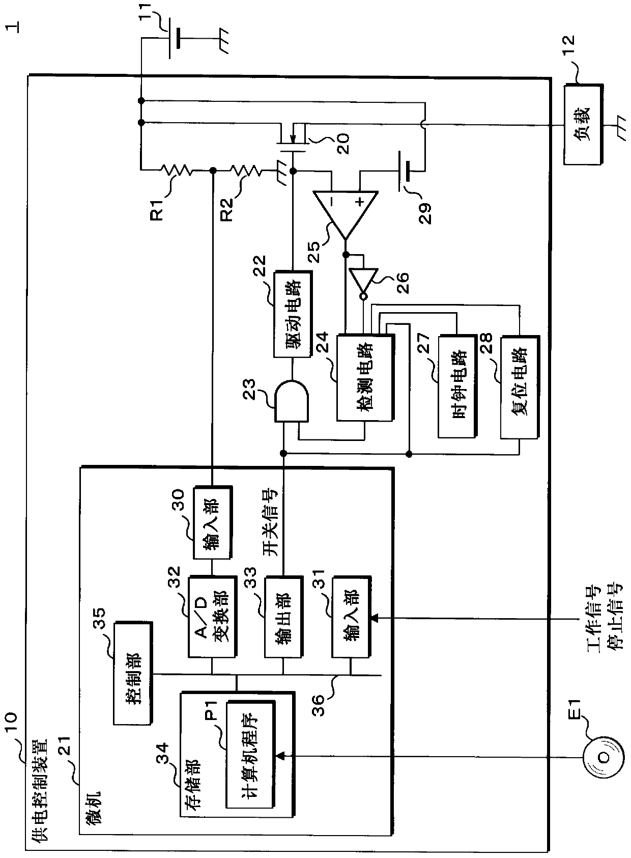
[0043] figure 1 It is a block diagram showing the configuration of main components of the power supply system 1 according to the first embodiment. The power supply system 1 is appropriately mounted on a vehicle, and includes a power supply control device 10 , a battery 11 , and a load 12 . The power supply control device 10 is respectively connected to the positive pole of the storage battery 11 and one end of the load 12 . The negative electrode of the storage battery 11 and the other end of the load 12 are grounded.

[0044] The storage battery 11 supplies electric power to the load 12 via the power supply control device 10 . The load 12 is an electrical device mounted on the vehicle. When the battery 11 supplies electric power to the load 12, the load 12 operates, and when the power supply from the battery 11 to the load 12 stops, the load 12 stops operating.

[0045] An operation signal instructing the load 12 to operate and a stop signal instructing the operation of t...

Embodiment approach 2

[0142] Figure 9 It is a block diagram showing the configuration of main parts of the power supply system 1 according to the second embodiment.

[0143] Hereinafter, regarding Embodiment 2, points different from Embodiment 1 will be described. The configuration other than the configuration described later is the same as that of the first embodiment, and therefore the same components as those of the first embodiment are given the same reference numerals as those of the first embodiment, and descriptions thereof are omitted.

[0144] The power supply system 1 of the second embodiment includes the same components as the power supply system 1 of the first embodiment. Furthermore, the power supply control device 10 according to the second embodiment has the same constituent elements as the power supply control device 10 according to the first embodiment. When the second embodiment is compared with the first embodiment, the connection of the comparator 25 and the DC power supply 2...


PUM


Abstract

A power supply control device and a power supply control method capable of detecting a switch-related failure properly are provided. A power supply control device controls power supply via a switch. An output unit of a microcomputer produces a switching signal that instructs the switch to turn alternately on and off. A detection circuit reports a failure related to the switch if an accumulated period has reached or exceeded a threshold period. The accumulated period is accumulation of one or more periods when the switching signal instructs the switch to turn on but a comparator does not detectan on-state of the switch.

Description

technical field [0001] The invention relates to a power supply control device and a power supply control method. Background technique [0002] A power supply control device that controls power supply from a battery to a load is mounted on a vehicle (for example, Patent Document 1). In the power supply control device described in Patent Document 1, the switch is switched on or off based on a switch signal instructing on or off of a switch provided on a current path from the battery to the load. Accordingly, power supply to the load is controlled. [0003] When the switch is turned on, the voltage between the two ends of the switch is approximately 0V, and when the switch is turned off, the voltage between the two ends of the switch is relatively high. In the power supply control device described in Patent Document 1, although the switch signal indicates ON, if the voltage value between both ends of the switch is equal to or greater than a certain voltage value for a predete...

Claims


Application Information

Patent Timeline
Patent Type & Authority Applications(China)
IPC IPC(8): H02J7/00
CPCH02J7/0063H02J7/007182H03K17/08122H03K5/1565
Inventor 泽野峻一杉泽佑树
Owner AUTONETWORKS TECH LTD
Why Eureka
Try Eureka