Eureka AIR delivers breakthrough ideas for toughest innovation challenges, trusted by R&D personnel around the world.

Elevator control system

A technology of elevator control and elevator control device, which is applied in elevators, transportation and packaging, etc., and can solve problems such as complex circuit structure of the control system

Active Publication Date: 2008-06-18
HITACHI LTD +2
View PDF1 Cites 0 Cited by
  • Summary
  • Abstract
  • Description
  • Claims
  • Application Information

AI Technical Summary

Problems solved by technology

[0004] In order to detect the failure of the speed monitoring control device, the speed information detected according to the pulse signal output by the encoder installed on the speed governor is sent to the elevator control In the case of a device, it is necessary to have a plurality of signal lines like a parallel communication circuit, or to have a program for communication processing like a serial communication, so there is a problem that the circuit structure of the control system becomes complicated.

Method used


Image

  • Elevator control system
  • Elevator control system
  • Elevator control system

Examples


Embodiment Construction

[0019] Hereinafter, embodiments of the present invention will be described with reference to the drawings.

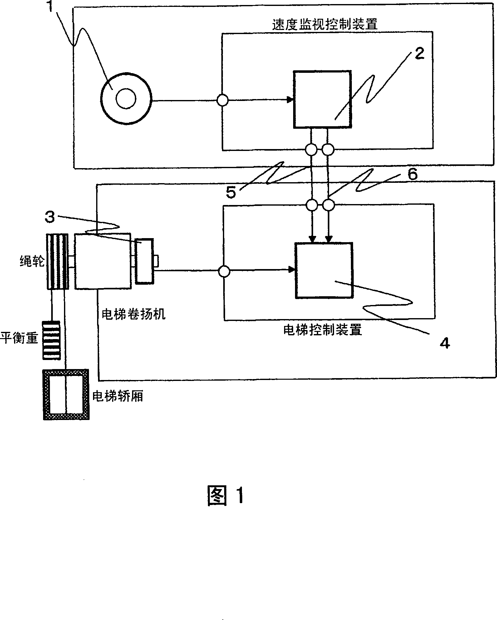
[0020] Fig. 1 shows an elevator control system as an embodiment of the present invention.

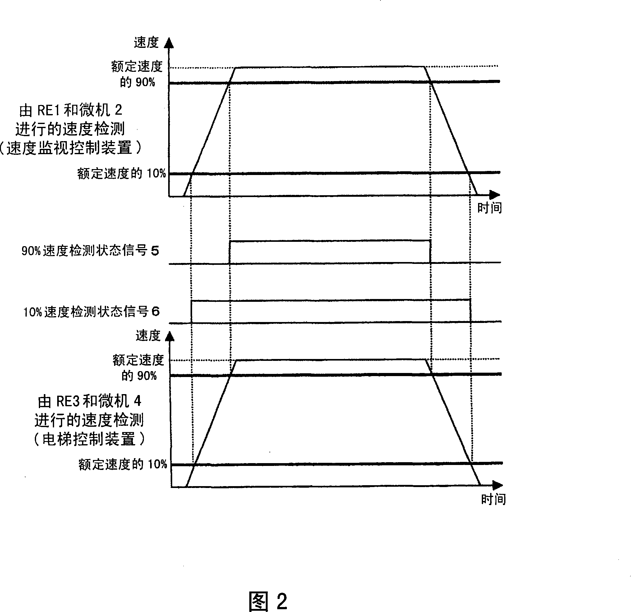
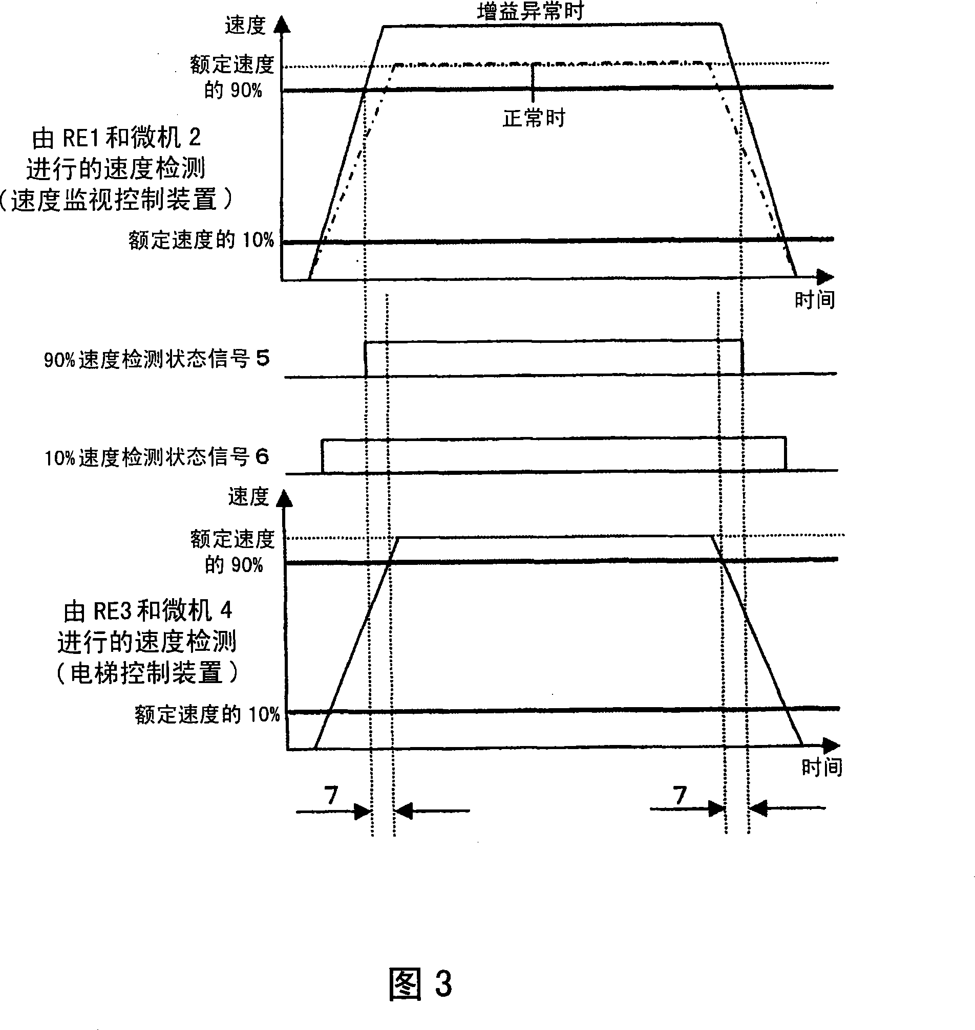
[0021] The speed monitoring control device for monitoring the speed of an elevator is composed of a rotary encoder 1 (hereinafter referred to as RE1) as a speed detector and a microcomputer 2 (hereinafter referred to as microcomputer 2) for processing the output signal of RE1. Here, RE1 is attached to a governor (not shown), and outputs a pulse signal according to the rotation of the governor sheave. The speed monitoring control device calculates the running speed of the elevator car by computing the pulse signal of RE1 through the microcomputer 2, and outputs a speed information signal when the running speed reaches a predetermined speed. In this embodiment, the speed information signal refers to the 10% speed detection state signal 5 output when the travel speed reaches more t...


PUM


Abstract

The invention relates to an elevator control system which can detect a speed monitor control device fault by an easier structure. The speed monitor control device respectively outputs a speed information signal, when an elevator speed operated by the output signal of a first speed detector reaches a first speed below a rated speed, and reaches a second speed below the rated speed and faster than the first speed. In addition, the elevator control device detects the abnormity of the first speed detector according to the speed information signal and the elevator speed operated by the elevator control device according to the output signal of the second speed detector.

Description

technical field [0001] The invention relates to an elevator control system for detecting elevator speed. Background technique [0002] As the prior art, it is known, for example, that a technical solution is disclosed in Japanese Patent Application Laid-Open No. 2006-44894 of Patent Document 1, which includes being installed on the hoisting machine of the elevator for outputting the control in the elevator control device. The speed or position control signal encoder and the encoder installed on the governor (governor) independently of the above encoder and the speed of the elevator car are monitored based on the output signal of the independently installed encoder. The speed monitoring control device, wherein the overspeed detection level of the governor is changed according to the position of the elevator car, and when the speed of the elevator car reaches the overspeed level, the elevator car is forcibly decelerated and stopped. [0003] Patent Document 1: Japanese Patent...

Claims


Application Information

Patent Timeline
IPC IPC(8): B66B1/24B66B5/06
Inventor 田中圭一铃木靖孝深田裕纪古桥昌也岸川孝生大木茂池富力筱塚广树佐藤康一羽田诚秀铃木雄一郎
Owner HITACHI LTD
Why Eureka
Eureka Blog
Learn More