
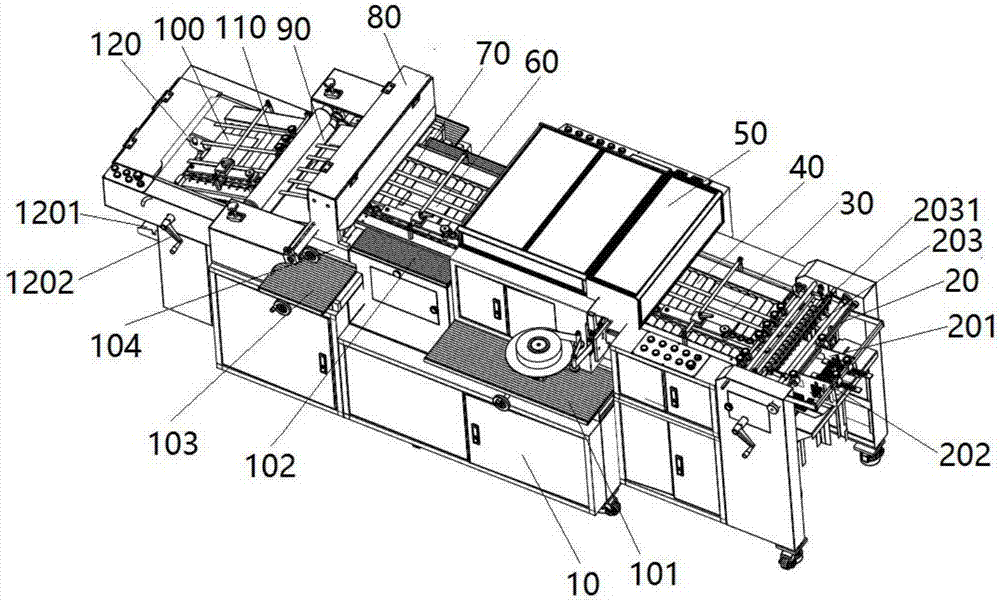
Paper film pasting, die cutting and forming equipment

A paper and film technology, applied in the field of paper film pasting die-cutting molding equipment, can solve the problems of low production efficiency, high manual work intensity, and difficult quality assurance

Pending Publication Date: 2018-01-12
毛以波
View PDF0 Cites 4 Cited by
  • Summary
  • Abstract
  • Description
  • Claims
  • Application Information

AI Technical Summary

Problems solved by technology

Usually it is done manually on two machines one by one, not only the production efficiency is low, but the manual work intensity is high, and the length and effect of the film depends entirely on the operator, so the quality is difficult to guarantee.
It needs to be moved once during the processing, which is easy to cause pollution and damage the printed matter.
In view of the existing printing industry mentioned above, the film pasting and molding of the post-press processing paper are all manual operations. Therefore, it is very necessary to produce a fully automatic film pasting and forming machine.

Method used


Image

  • Paper film pasting, die cutting and forming equipment
  • Paper film pasting, die cutting and forming equipment
  • Paper film pasting, die cutting and forming equipment

Examples


Embodiment Construction

[0055] In order to further explain the technical means and effects of the present invention to achieve the intended purpose of the invention, the specific implementation, structure, features and effects of the application according to the present invention will be described in detail below in conjunction with the accompanying drawings and preferred embodiments. . In the following description, different "one embodiment" or "embodiment" do not necessarily refer to the same embodiment. Furthermore, the particular features, structures, or characteristics of one or more embodiments may be combined in any suitable manner. It should be noted that the "front" and "rear" mentioned in the embodiments of the present invention are all in the same direction, and the "front" and "rear" are opposite directions.

[0056] A paper film pasting die-cutting molding equipment, comprising:

[0057] The frame includes a first mobile platform arranged in the frame, a hand-adjustable slide table arr...


PUM


Abstract

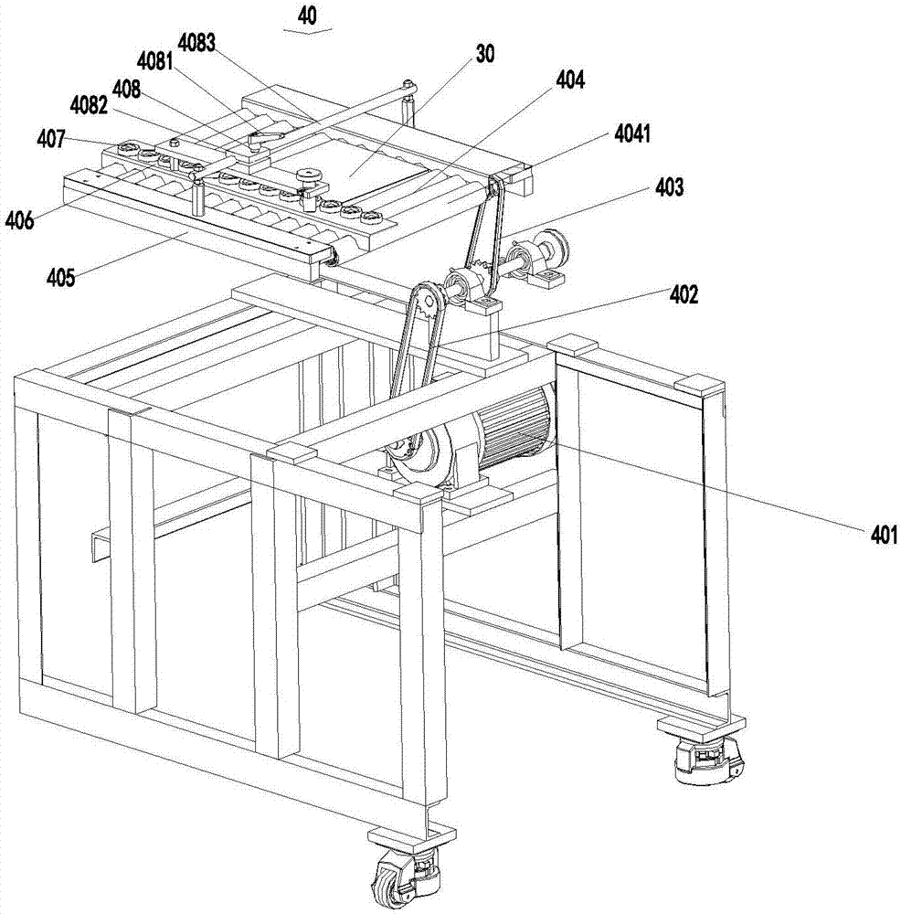
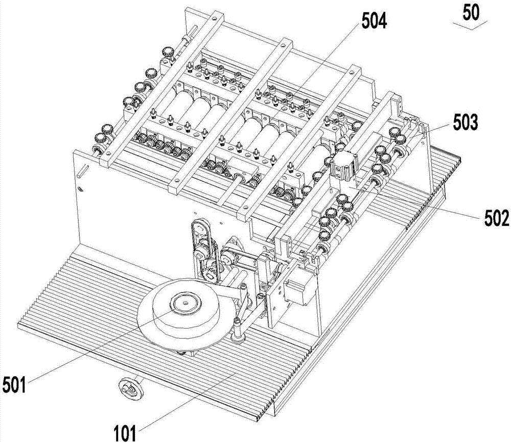
The invention discloses paper film pasting, die cutting and forming equipment. According to the main technical scheme, the paper film pasting, die cutting and forming equipment comprises a rack, a paper feeding mechanism, a paper first positioning and conveying mechanism, a film pasting mechanism, a paper second positioning and conveying mechanism, a film die cutting mechanism, a forming pressingroller mechanism, a paper collecting and positioning mechanism and a paper collecting mechanism, wherein the rack comprises a first moving platform arranged in the rack, a manual adjusting sliding platform arranged in the rack and a second moving platform arranged in the rack, and the second moving platform is provided with a third moving platform; the paper feeding mechanism is arranged at the front end of the rack; the paper first positioning and conveying mechanism is arranged on the rack and located behind the paper feeding mechanism; the film pasting mechanism is arranged on the first moving platform and located behind the paper first positioning and conveying mechanism; the paper second positioning and conveying mechanism is arranged on the manual adjusting sliding platform and located behind the film pasting mechanism; the film die cutting mechanism is located behind the paper second positioning and conveying mechanism; the forming pressing roller mechanism is located behind thefilm die cutting mechanism; the paper collecting and positioning mechanism is fixed to the rack and located behind the forming pressing roller mechanism; and the paper collecting mechanism is fixed to the rack and located behind the paper collecting and positioning mechanism.

Description

technical field [0001] The invention relates to the technical field of production equipment for post-press processing paper glue index pasting in the printing industry, in particular to a paper film pasting die-cutting molding equipment Background technique [0002] At present, in the post-press processing of the printing industry, the film sticking of paper is mainly done manually on a semi-automatic glue index pasting machine one by one; Die cut to form. Usually, it is done manually on two machines one by one. Not only is the production efficiency low and the manual work is intensive, but also the length and effect of the film depends entirely on the operator, and the quality is difficult to guarantee. It needs to be handled once during processing, which is easy to cause pollution and damage the printed matter. For the existing printing industry mentioned above, the film pasting and molding of the post-press processing paper are all the shortcomings of manual operation. ...

Claims


Application Information

Patent Timeline
IPC IPC(8): B29C65/18B29C65/78B26F1/38B26D7/27
Inventor 毛以波
Owner 毛以波
Learn More