
Wind-proof protecting wall used for construction site

A technology for construction sites and protective walls, applied in construction, protective equipment, etc., can solve the problems of only dismantling, troublesome paving, easy to dump, etc., to avoid being blown over by the wind and facilitate transportation.

Active Publication Date: 2018-01-12
WENZHOU UNIV OUJIANG COLLEGE
View PDF4 Cites 8 Cited by
  • Summary
  • Abstract
  • Description
  • Claims
  • Application Information

AI Technical Summary

Problems solved by technology

[0002] Usually, when carrying out various construction projects in the city, in order to ensure the beauty of the city and protect the safety of pedestrians, and to prevent the gravel and residue generated during the construction process from flying out of the outside and hurting nearby people, temporary or semi-temporary protection will be used. The wall encloses the building construction area. The existing protective walls mainly include the following types: one is the clay bricks built with traditional techniques, which are heavy-duty walls, and the construction speed is extremely slow and the walls can only be demolished in the end. It is a great waste of resources and manpower, and increases construction waste; one is the color steel plate protective wall, but the color steel plate wall is poor in usability, it is easy to topple in strong winds, and has poor wind resistance. If it is adjacent to the sidewalk, it is easy to hit Pedestrians; there is also a protective net with the entire structure, which is very troublesome to install and also has the problem of poor wind resistance. In the process of use, due to the aging of the protective net or damage during construction, it needs to be repaired in the middle period. The overall structural strength of the repaired protective net is lower, and the possibility of subsequent reuse is lower, which will also increase the construction cost

Method used


Image

  • Wind-proof protecting wall used for construction site
  • Wind-proof protecting wall used for construction site
  • Wind-proof protecting wall used for construction site

Examples


Embodiment 1

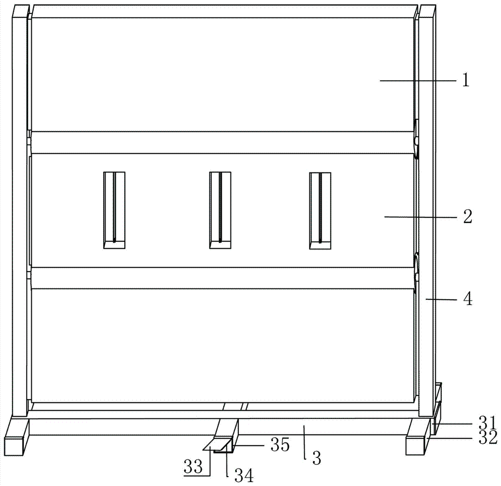
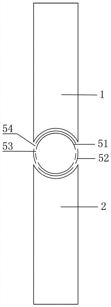
[0022] refer to Figure 1-4 As shown, a wind-resistant protective wall for a construction site in this embodiment includes several repeating units, and each unit includes two first guard plates 1, second guard plates 2, base 3 and two installation columns 4. The base 3 includes a hollow horizontal support rod 31 and a number of hollow longitudinal support rods 32. The horizontal support rod 31 and the longitudinal support rod 32 intersect vertically. The ends of the horizontal support rod 31 and the longitudinal support rod 32 are hinged with a cover plate 33 , the inner surface of the cover plate 33 is provided with a magnetic piece 34, a lead weight 35 is inserted in the horizontal support rod 31 and the longitudinal support rod 32, and the end of the lead weight 35 is fixed with an iron sheet; the bottom ends of the two mounting columns 4 are fixed on the horizontal At both ends of the support rod 31, two first guard plates 1 are symmetrically arranged on the upper and lowe...

Embodiment 2

[0028] refer to Figure 5-8 As shown, a wind-resistant protective wall for a construction site in this embodiment includes several repeating units, and each unit includes two first guard plates 1, second guard plates 2, base 3 and two installation columns 4. The base 3 includes a hollow horizontal support rod 31 and a number of hollow longitudinal support rods 32. The horizontal support rod 31 and the longitudinal support rod 32 intersect vertically. The ends of the horizontal support rod 31 and the longitudinal support rod 32 are hinged with a cover plate 33 , the inner surface of the cover plate 33 is provided with a magnetic piece 34, a lead weight 35 is inserted in the horizontal support rod 31 and the longitudinal support rod 32, and the end of the lead weight 35 is fixed with an iron sheet; the bottom ends of the two mounting columns 4 are fixed on the horizontal At both ends of the support rod 31, two first guard plates 1 are symmetrically arranged on the upper and lowe...

Embodiment approach

[0033] As an improved specific embodiment, it also includes a corner assembly, the corner assembly includes a support column 81 and two corner plates 82, the side of the corner plate 82 is hinged on the support column 81, and the other side of the corner plate 82 is connected with The arc-shaped connecting plate 83 is hooped on the outer wall of the mounting column 4 , and the bottom end of the connecting plate 83 is fixed on the transverse support bar 31 . Because the side of the corner plate 82 is hinged on the support column 81, the corner assembly can adapt to the needs of corners of various radians, and the arc-shaped connecting plate 83 is hooped on the outer wall of the installation column 4, so that the installation column 4 can fix the corner assembly. And the connecting plate 83 can be rotated along the mounting column 4 according to the actual rotation angle range.

[0034] As an improved specific embodiment, a third hollow groove 21 is arranged on the surface of th...


PUM


Abstract

The invention discloses a wind-proof protecting wall used for a construction site. The wind-proof protecting wall comprises a plurality of repeating arrangement units, each repeating arrangement unitcomprises two first protecting plates, a second protecting plate, a base and two mounting columns, the base comprises a hollow transverse supporting rod and a plurality of hollow longitudinal supporting rods, cover plates are hinged to the end portions of the transverse supporting rod and the longitudinal supporting rods, the inner side face of each cover plate is provided with a magnetic block, lead blocks are inserted in the transverse supporting rod and the longitudinal supporting rods, and an iron piece is fixed at the end of the lead block; the bottom ends of the two mounting columns arefixed at the two ends of the transverse supporting rod, and the two first protecting plates are symmetrically arranged on the upper side and the lower side of the second protecting plate; and the twosides of the second protecting plate are correspondingly fixed on the mounting columns, the two ends of each first protecting plate are rotatably connected to the mounting columns, and a passive ventilation device is arranged between the first protecting plates and the second protecting plate. All the units of the wind-proof protecting wall can be disassembled and mounted, and the wind-proof protecting wall can be transported conveniently and reutilized and can avoid being blown down by wind while playing a protecting role.

Description

technical field [0001] The invention relates to the field of construction, and more specifically relates to a wind-resistant protective wall for a construction site. Background technique [0002] Usually, when carrying out various construction projects in the city, in order to ensure the beauty of the city and protect the safety of pedestrians, and to prevent the gravel and residue generated during the construction process from flying out of the outside and hurting nearby people, temporary or semi-temporary protection will be used. The wall encloses the building construction area. The existing protective walls mainly include the following types: one is the clay bricks built with traditional techniques, which are heavy-duty walls, and the construction speed is extremely slow and the walls can only be demolished in the end. It is a great waste of resources and manpower, and increases construction waste; one is the color steel plate protective wall, but the color steel plate wa...

Claims


Application Information

Patent Timeline
IPC IPC(8): E01F7/02
Inventor 王艳茹张茂雨郑淑琴符斌朱丽毛华庆
Owner WENZHOU UNIV OUJIANG COLLEGE
Learn More