
Blade fixed structure and UAV

A fixed structure and blade technology, applied in the field of flight devices, can solve problems such as potential safety hazards, achieve the effects of rapid installation and disassembly, ensure flight safety, and facilitate operation

Active Publication Date: 2019-09-27
GUANGZHOU XAIRCRAFT TECH CO LTD
View PDF8 Cites 1 Cited by
  • Summary
  • Abstract
  • Description
  • Claims
  • Application Information

AI Technical Summary

Problems solved by technology

These two methods of quick installation, disassembly and fixing of the blades, when the motor decelerates too fast, because the blades still have a lot of kinetic energy to keep rotating, the paddles will fly out in the direction of loosening, posing a certain safety hazard

Method used


Image

  • Blade fixed structure and UAV
  • Blade fixed structure and UAV
  • Blade fixed structure and UAV

Examples


Embodiment Construction

[0025] Embodiments of the present invention are described in detail below, examples of which are shown in the drawings, wherein the same or similar reference numerals designate the same or similar elements or elements having the same or similar functions throughout. The embodiments described below by referring to the figures are exemplary only for explaining the present invention and should not be construed as limiting the present invention.

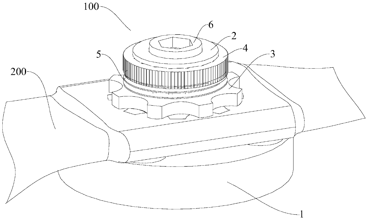
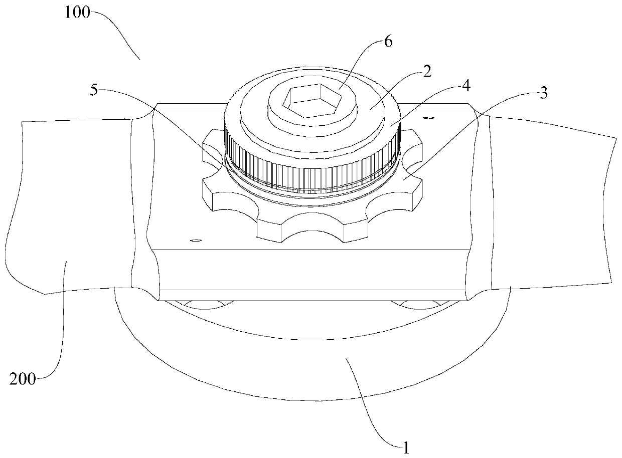
[0026] Refer below Figure 1-Figure 5 A blade fixing structure 100 according to an embodiment of the present invention is described.

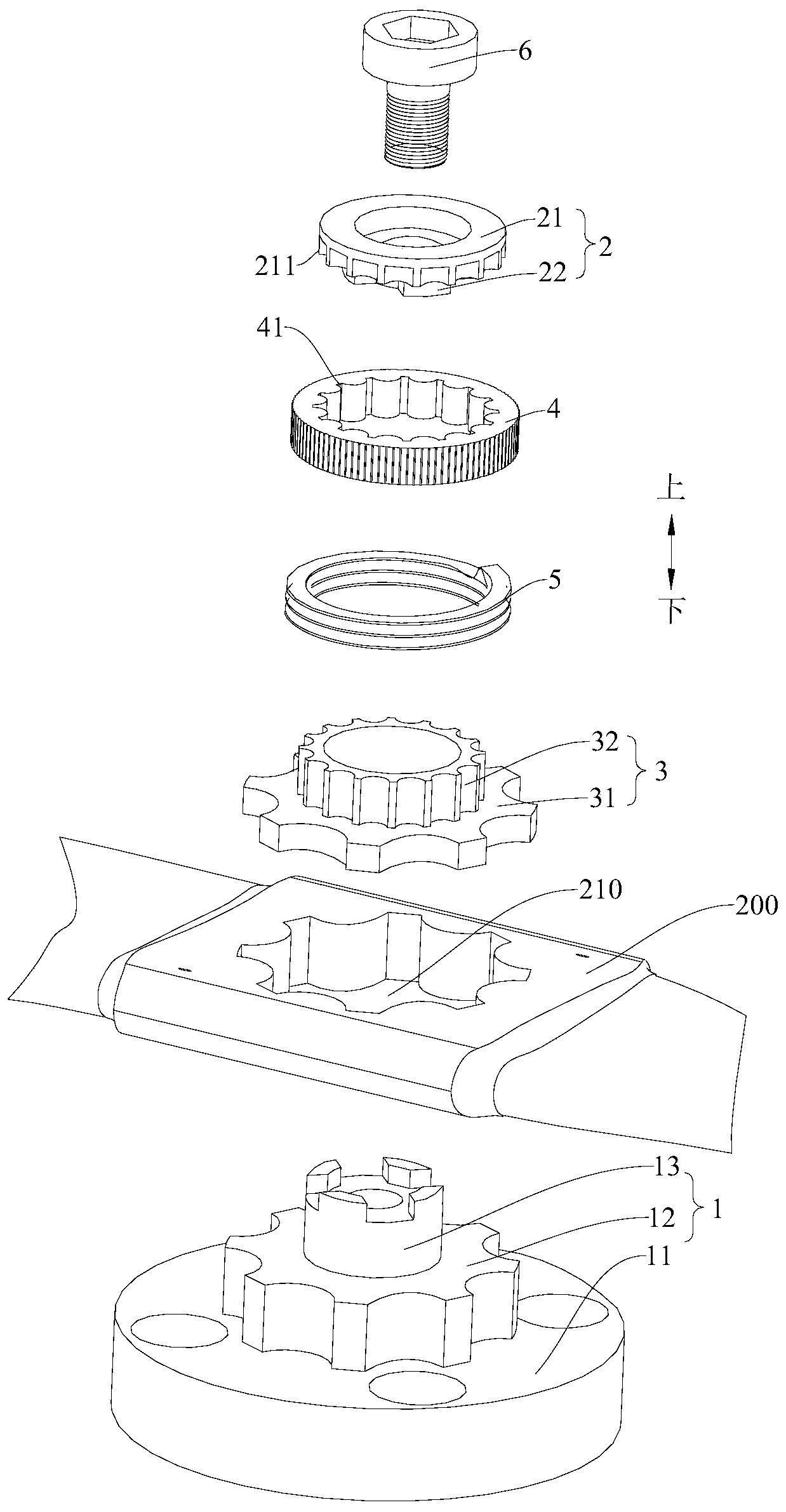
[0027] Such as Figure 2-3 As shown, according to the blade fixing structure 100 of the embodiment of the present invention, the blade fixing structure 100 is used to quickly install the blade 200 on the motor (not shown in the figure), and the blade 200 is provided with a mounting channel hole 210 , the installation through hole 210 is a non-circular hole, and the paddle fixing structure 100 includes: ...


PUM


Abstract

A blade fixing structure and an unmanned aerial vehicle are disclosed. The blade fixing structure is used for rapidly mounting a blade to a motor. The blade fixing structure includes a base includinga rotation limiting block having a shape matched with a mounting through hole, with the rotation limiting block being fixed to the motor; a blocking element including an upper blocking table connectedto the rotation limiting block; an axial limiting element rotatably disposed between the upper blocking table and the rotation limiting block, and having a shape matched with the mounting through hole; and an elastic element disposed between the axial limiting element and the blocking element, and pressing the axial limiting element against the rotation limiting block. According to the blade fixing structure, the blade can be rapidly dismounted.

Description

technical field [0001] The invention belongs to the technical field of flying devices, and in particular relates to a blade fixing structure and an unmanned aerial vehicle. Background technique [0002] The fast installation and disassembly of the existing UAV blades are usually fixed by positive and negative threads, or the positive and negative screw position is pressed against the limit card slot by the shrapnel. These two methods of quick installation, disassembly and fixing of the blades, when the motor decelerates too fast, because the blades still have a lot of kinetic energy to keep rotating, the paddles will fly out in the direction of loosening, posing a certain safety hazard. Contents of the invention [0003] The present invention aims to solve at least one of the technical problems existing in the prior art. For this reason, the present invention proposes a blade fixing structure, which can facilitate fast fixing of the blade and prevent the blade from flying...

Claims


Application Information

Patent Timeline
Patent Type & Authority Patents(China)
IPC IPC(8): B64C11/16B64C11/00
Inventor 邓晓文
Owner GUANGZHOU XAIRCRAFT TECH CO LTD
Learn More