[0056] In order to have a clearer understanding of the technical features, objectives and effects of the present invention, the specific embodiments of the present invention will now be described in detail with reference to the accompanying drawings.
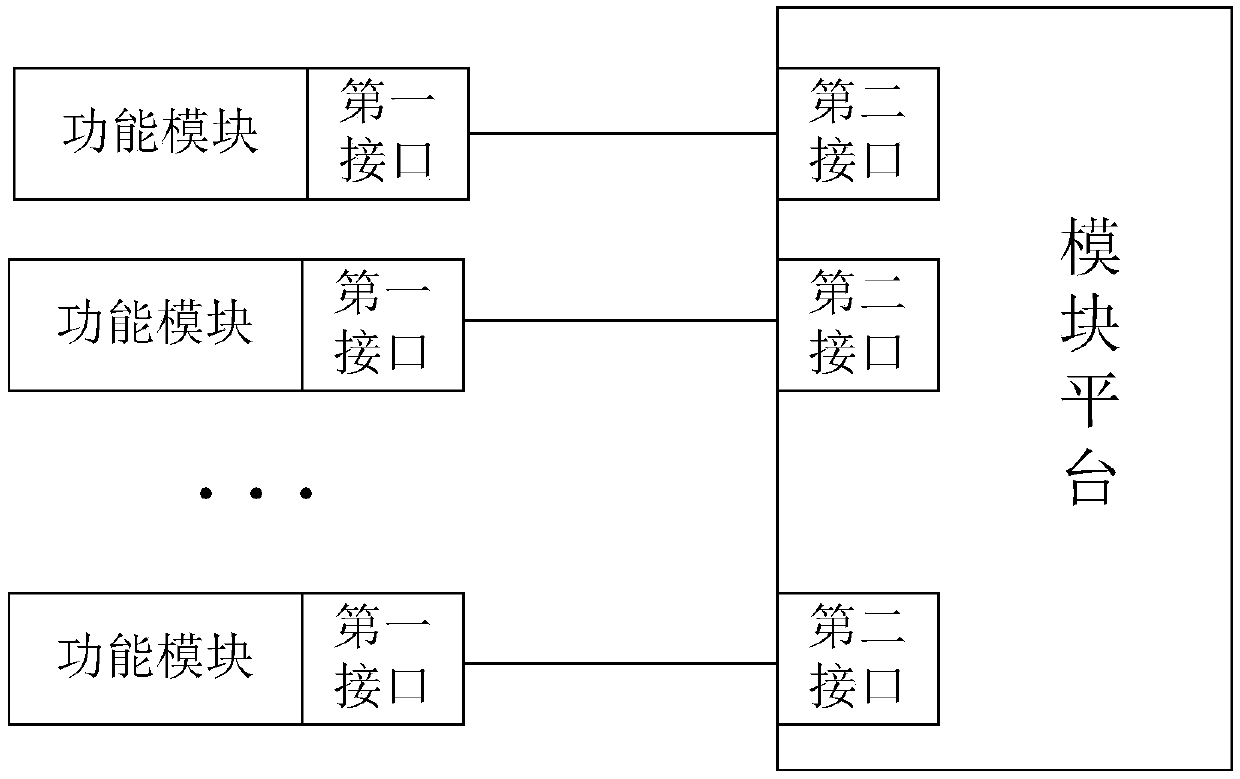
[0057] figure 1 It is a schematic diagram of the structure of the communication interface connecting the functional module and the module platform of the present invention.
[0058] Specifically, the communication interface of the present invention is used to connect and implement the communication between the module platform and the functional module. Preferably, smart terminals include but are not limited to smart phones, smart bracelets, smart glasses, etc.; smart terminals use Android operating systems, IOS operating systems, Windows operating systems, Linux operating systems, etc. Functional modules include but are not limited to: battery module, air module, water module, bracelet module, Bluetooth headset module, positioning module, distance detection module, temperature detection module, storage module, NFC module, wireless charging module, etc.
[0059] The communication interface includes: a first interface set on the functional module and a second interface set on the module platform, and the first interface and the second interface match. The module platform may include a plurality of second interfaces, and the module platform is connected to the first interface of the functional module through each second interface to realize the expansion of one functional module.
[0060] Alternatively, the first interface and the second interface are 8-pin interfaces, including: the first pin VIN, the second pin DET0, the third pin DET1, the fourth pin VOUT, the fifth pin GND, and the sixth pin. Pin DM, seventh pin DP, and eighth pin GND. The following limits the function of each pin:
[0061] The first pin VIN is used for the power access of the functional module, used for the first type of functional module and the second type of functional module. The division of the first type of functional module and the second type of functional module is through the second pin DET0 and the second pin. Three-pin DET1 implementation.
[0062] The second pin DET0 and the third pin DET1 are used to classify the functional modules. The functional modules are divided into four categories according to the impedance of the second pin DET0 and the third pin DET1:
[0063] The first type of functional module: The functional module is an empty module or an idle module. This type of module only needs to be plugged into the module platform, and no signal enters or outputs.
[0064] The second type of functional module: The functional module is the first type of power supply module. This type of module requires the module platform to provide electrical characteristics for it, that is, provide electrical energy and communicate. Preferably, if the module platform is a module frame, and the module frame is used to connect an intelligent terminal, the second type of functional module is directly connected to the module frame for use.
[0065] The third type of functional module: The functional module is the second type of power supply module. This type of module requires the module platform to provide electrical characteristics for it, that is, provide electrical energy and communicate. Preferably, if the module platform is a module frame, and the module frame is used to connect an intelligent terminal, the second type of functional module is directly connected to the intelligent terminal for use. For example, the third type of functional module is a storage module. If the storage module transfers the data to the smart terminal after being processed by the module frame, the data transmission rate will be slow, and the requirements for the processor of the module frame will be relatively high. The cost rises, so this type of module needs to directly interact with the smart terminal without intermediate transfer, thereby increasing the data transmission rate.
[0066] The fourth type of functional module: The functional module is a battery or a charging device, and the battery can be charged through VIN.
[0067] The fourth pin VOUT is used for the power output of the functional module;
[0068] The fifth pin GND and the eighth pin GND are grounded;
[0069] The sixth pin DM and the seventh pin DP are used to transmit data content.
[0070] It is understandable that the arrangement sequence of the eight pins of the communication interface can be adjusted as required, and the present invention does not limit this. The number and functions of the pins are the same as those of the present invention and fall within the protection scope of the present invention.
[0071] Figure 2a with Figure 2b It is a pin structure diagram of a communication interface of the present invention.
[0072] Specifically, the Figure 2a Among them, the 8 pins of the first interface correspond to the 8 pins of the second interface. The 8 pins of the first interface and the second interface are distributed in two rows, with four pins in each row, and the pins in each row are equally spaced. Or in Figure 2b In this case, the 8 pins of the first interface and the second interface are arranged in a row, that is, the 8 pins are arranged in a row. It can be understood that the distribution of the eight pins of the communication interface can be adaptively adjusted according to the shape and connection position of the functional module and the module platform.
[0073] image 3 It is a schematic diagram of the connection mode of the module platform and the functional modules of the present invention.
[0074] Specifically, a plurality of second interfaces are provided on the module platform, and each second interface corresponds to a slot for installing a functional module, the slots are arranged in parallel, and the functional modules are connected to the module frame through one or more slots. The functional module is inserted into the slot, and is connected to the second interface of the module platform through the first interface, thereby realizing the connection with the module platform. Optionally, the functional module can be one slot plugged into one functional module, or one module occupies multiple slots. E.g image 3 In the module platform, there are four second interfaces, corresponding to four slots, which can be a single-slot functional module with one functional module corresponding to one slot, or a two-in-one with one functional module corresponding to two slots The interface can also be a four-in-one interface with one functional module corresponding to four slots. It is understandable that when one module corresponds to multiple slots, the first interface may be one or more.
[0075] Alternatively, the functional modules in the present invention can be a single function or multiple functions, and can be combined as required. If it is a single functional module, only one first interface is required; if it is a multi-functional module, there may be multiple first interfaces.
[0076] Figure 4 It is a diagram of the preset data frame format for data transmission through a communication interface of the present invention.
[0077] Specifically, the communication interface is used for the connection and communication between the functional module and the module platform. The communication interface transmits data through a preset data frame. The preset data frame includes: preamble field (preamble), command code field (command field), sequence Number field (serial number), data length field (data length), data content field (data), check code field (checksum); among them,
[0078] The leading field is a synchronization header, which is used to indicate the flow direction of the data stream. Its byte is fixed. There are two transmission modes: one is the module platform initiates to the functional module, the other is the functional module initiates to the module platform.
[0079] The command code field is a communication command between the function module and the module platform. As a communication command, the present invention is provided with a command list, which is stored in the function module and the module platform respectively for encoding and decoding.
[0080] The serial number field is the serial number automatically generated by the system composed of the module platform and functional modules, and the corresponding reply command uses the same serial number, and only the initiator has the serial number generated by the system.
[0081] The data content field is the transmission data content, and the transmission data content includes commands and data sent by the module platform to the function module, and collected data sent by the function module to the module platform. For example, temperature data and positioning information collected by functional modules.
[0082] The data length field is the length of the data content to be transmitted, and the length of the data content can be set as needed to meet the data transmission requirements; for example, 255 bytes, 1024 bytes, etc.
[0083] The check code field is used to check the preset data frame. After the transmission of the preset data frame is completed, it is necessary to detect whether the data frame has an error during the transmission process, and perform data correction through verification. The present invention does not limit the method of data verification, as long as the data verification can be performed. For example, CRC (Cyclic Redundancy Check) or BCC (BlockCheck Character) is used.
[0084] Figure 5 It is a schematic diagram of the communication process between the functional module and the module frame of the present invention.
[0085] Specifically, the functional modules use the aforementioned communication interface to connect to the module frame, the module frame is used to connect to the smart terminal, and the communication protocol used by the communication interface includes: knocking protocol, module control protocol, and data exchange protocol.
[0086] The knock-on protocol is used for the discovery and detection of functional modules. The data of the knock-on protocol is defined as: data type (1 byte) + data mode supported by the module (1 byte) + 2 bytes (extended). For example, the knocking agreement is shown in Table 1:
[0087] Table 1
[0088] Command header
[0089] Take air module and wristband module as examples, the module type definition is shown in Table 2:
[0090] Table 2
[0091] Module name
[0092] The module control protocol is used to set the configuration and adjustment command types of functional modules;
[0093] The data exchange protocol is used for data download and upload.
[0094] Image 6 It is a schematic flow diagram of the communication method between the functional module and the module frame of the present invention.
[0095] Specifically, in the communication method between the function module and the module frame of the present invention, the HID (Human Interface Device) protocol is used as the underlying communication basic protocol between the module frame and the function module, and the application data packet uses a preset data frame. The communication between the function module and the module framework includes the following steps:
[0096] S1: After the functional module is plugged into the module frame, the module frame recognizes the module type of the functional module, and during the identification process, the module frame does not supply power to the functional module;
[0097] S2: After the module framework identifies the type of the functional module, it performs power supply and/or connection operations for the functional module;
[0098] S3: The function module sends the knocking protocol to the module frame;
[0099] S4: The module frame establishes a communication connection with the functional module according to the knock-on protocol.
[0100] Preferably, the communication interface for the command frame and the functional module transmits data through a preset data frame, the length of the preset data frame is not greater than 260 bytes, and the little-endian mode is adopted. Specifically, in the preset data frame: the data length of the preamble field, the command code field, the serial number field, the data length field, and the check code field is 1 byte, the data length of the data content field is N bytes, and N is Natural number.
[0101] The leading field is a synchronization header, which is used to indicate the flow direction of the data stream. Its byte is fixed. There are two transmission modes: one is the module frame to initiate the function module, the other is the function module to the module frame.
[0102] The command code field is a communication command between the function module and the module frame. As a communication command, the present invention is provided with a command list. The command list is stored in the function module and the module frame respectively for encoding and decoding.
[0103] The serial number field is the serial number automatically generated by the system composed of the module framework and functional modules. The corresponding reply command uses the same serial number. Only the initiator has the serial number generated by the system.
[0104] The data content field is the transmission data content, and the transmission data content includes commands and data sent by the module framework to the function module, and collected data sent by the function module to the module framework. For example, temperature data and positioning information collected by functional modules.
[0105] The data length field is the length of the transmitted data content, and the maximum length is 255 bytes.
[0106] The check code field is used to check the preset data frame. After the transmission of the preset data frame is completed, it is necessary to detect whether the data frame has an error during the transmission process, and perform data correction through verification. The verification code field is verified by BCC verification.
[0107] The above principles are further explained by the air module and the bracelet module below.
[0108] For the air module, the air module needs to report the knocking protocol after it is powered on, and the data in the knocking protocol is defined as above.
[0109] The air module adopts the command code of the Internet of Things module, all command codes are defined in the value between 0X10-0X1F, and the value of the corresponding command is specified in this interval when the command is added later.
[0110] Command name: Get current air index data.
[0111] Command code value: 0X10.
[0112] Command description: Obtain the data values of the air indicators of the air module at this time.
[0113] Application scenario: The framework communicates with the air module through this command to obtain air-related data at this time.
[0114] The format of the obtained data is shown in Table 3:
[0115] table 3
[0116] Command header
[0117] The returned data format is shown in Table 4:
[0118] Table 4
[0119] Command header
[0120] Data format definition:
[0121] Air return data: little endian 4 bytes of air data, or 0xFFFFxxxx, where 0xFFFF indicates an error return, and xxxx indicates an error code.
[0122] For the bracelet module, the bracelet module needs to report the knock protocol after power-on. The data in the knock protocol is defined as above.
[0123] Define all command codes of the bracelet module in the value between 0X20~0X2F, and specify the value of the corresponding command in this interval when adding commands later.
[0124] Command name: Get bracelet data.
[0125] Command code value: 0X20.
[0126] Command description: Get the data of the bracelet module.
[0127] Application scenario: The framework downloads all data of the bracelet through this instruction.
[0128] The format of the obtained data is shown in Table 5:
[0129] table 5
[0130] Command header
[0131] The returned data format is shown in Chart 6:
[0132] Table 6
[0133] Command header
[0134] Data format definition:
[0135] Air return data: The length is returned by the module. When an error occurs, it returns 4 bytes 0xFFFFxxxx, where 0xFFFF indicates an error return, and xxxx indicates an error code.
[0136] Figure 7 It is a schematic diagram of the system structure of a module frame and an intelligent terminal of the present invention.
[0137] Specifically, the functional module establishes a connection and communicates with the module frame through the communication interface of the present invention, and the module frame connects and communicates with the intelligent terminal. For example, the smart terminal is a smart phone, and the module frame is a mobile phone back shell. The above-mentioned communication interface is used between the functional module and the module frame, and the intelligent terminal is installed with a management APP for managing the module frame and the functional module.
[0138] The intelligent terminal communicates with the module frame, and the module frame communicates with the functional module through the communication interface.
[0139] Preferably, in the communication method between the module frame of the present invention and the smart terminal, the communication interface transmits data through a preset data frame. In the preset data frame: preamble field, command code field, serial number field, data length field, and check code The data length of the field is 4 bytes, the data length of the data content field is N bytes, and N is a natural number.
[0140] The preamble field is a synchronization header, which is used to indicate the flow direction of the data stream. Its byte is fixed. There are two transmission methods: one is the module frame to initiate the smart terminal, and the other is the smart terminal to the module frame.
[0141] The command code field is a communication command between the function module and the module frame. As a communication command, the present invention is provided with a command list, which is stored in the function module, the module frame and the intelligent terminal, respectively, for encoding and decoding.
[0142] The serial number field is the serial number automatically generated by the system composed of the smart terminal, the module frame, and the functional module. The corresponding reply command uses the same serial number, and only the initiator has the serial number generated by the system.
[0143] The data content field is the transmission data content, and the transmission data content includes commands and data sent by the module platform to the function module, and collected data sent by the function module to the module platform. For example, temperature data and positioning information collected by functional modules.
[0144] The data length field is the length of the transmitted data content, and the length of the data content is not greater than 1024 bytes. Preferably, if the data length is greater than 1024 bytes, the framed connection is sufficient.
[0145] The check code field is used to check the preset data frame. After the transmission of the preset data frame is completed, it is necessary to detect whether the data frame has an error during the transmission process, and perform data correction through verification. The check code field is checked by the CRC check method.
[0146] Preferably, the command code field includes a connection request command field for the smart terminal to initiate a connection to the module frame. For example, the android host initiates a connection after the module frame is detected, and the subsequent service query can be carried out after the module frame responds. The field value is 0x4E584E43. The smart terminal initiates a disconnection command field to the module frame; for example, the android host initiates the disconnection of the module frame, and the subsequent command field cannot be transmitted after the module frame sounds. The field value is 0x45534C43, or the module is detected After the frame is unplugged, it will automatically be in the CLOSE state. The synchronization command field sent by the module framework at a preset time interval, for example, is initiated by the framework automatically every 5 seconds, and the field value is 0x434E5953. If this field is not received, it means that the connection is abnormal.
[0147] The system composed of the smart terminal, the module frame, and the functional modules will be described in detail below through the embodiments.
[0148] Figure 8 It is a schematic diagram of the structure of the module frame and the intelligent terminal of the present invention.
[0149] Command word name: module frame control protocol.
[0150] Command word description: This protocol mainly describes the control method of module frame access detection and frame power acquisition.
[0151] Command word structure: as shown in Table 7, corresponding to frame access, frame disconnection, and power acquisition:
[0152] Table 7
[0153] Leading
[0154] Smart terminal response: as shown in Table 8, corresponding to frame access, frame disconnection, and power acquisition.
[0155] Table 8
[0156] Leading
[0157] Usage scenario: When the user starts to connect the module frame to a smart terminal (such as a mobile phone), it needs to make a connection judgment with the smart terminal. Or when the user removes the module frame from the smart terminal, the user needs to make a disconnection judgment with the smart terminal. In addition, the user wants to know whether the module frame has sufficient power, and if it is not sufficient, it can be charged.
[0158] Picture 9 It is a schematic diagram of the control structure of the battery module of the present invention.
[0159] Command word name: battery control protocol.
[0160] Command word description: This protocol mainly describes the charging/non-charging control of the battery module, and the way of obtaining power.
[0161] Command word structure: as shown in Table 9, corresponding to battery charging, not charging, and obtaining power.
[0162] Table 9
[0163]
[0164]
[0165] The smart terminal responds: as shown in Table 10, corresponding to battery charging, not charging, and obtaining power.
[0166] Table 10
[0167] Leading
[0168] Usage scenario: This is mainly for the user to control the use of the battery module. When the power of the module frame is low, the battery module can be controlled to charge the module frame; or when the power of the smart terminal (such as a mobile phone) is low, the battery module can be controlled to enter the smart terminal. Recharge. In addition, the power of the battery module can be obtained, and the battery module only needs to be charged each time.
[0169] About U disk control protocol.
[0170] Command word name: U disk control protocol.
[0171] Command word description: This protocol mainly describes U disk online monitoring, U disk password input, U disk read and write control methods.
[0172] Command word structure: as shown in Table 11, corresponding to U disk detection, U disk password matching, and U disk data reading and writing.
[0173] Table 11
[0174] Leading
[0175] Smart terminal reply: as shown in Table 12, corresponding to U disk detection, U disk password matching, and U disk data reading and writing.
[0176] Table 12
[0177]
[0178]
[0179] Usage scenario: This is mainly the user interacting with the U disk module. When the frame is inserted into the U disk, the user will be prompted to insert a large-capacity storage device, and the user will perform the corresponding operation. The U disk password is matched with the background, and the reading and writing of U disk data are all placed in the cloud, and the user controls by sending corresponding instructions.
[0180] Picture 10 It is a schematic diagram of the control structure of the air and water module of the present invention.
[0181] Command word name: air and water sensor control protocol.
[0182] Command word description: This protocol mainly describes the online detection of air and water sensor modules, as well as the way of acquiring primary data and all data.
[0183] Command word structure: as shown in Table 13, respectively corresponding to module detection, data acquisition, and data summary.
[0184] Table 13
[0185] Leading
[0186] Smart terminal reply: as shown in Table 14, corresponding module detection, acquisition of data, and data summary respectively.
[0187] Table 14
[0188] Leading
[0189] Usage scenario: This is mainly the interaction between the user and the air and water sensor modules. When the air and water sensor modules are inserted, the corresponding detection will be carried out and the user will be prompted. When users want to know the current air and water quality, they can perform a data query, or they can learn about the fluctuation graph of air and water quality data for 24 hours a day through data aggregation.
[0190] Picture 11 It is a schematic diagram of the control structure of the Bluetooth headset of the present invention.
[0191] Command word name: Bluetooth headset control protocol.
[0192] Command word description: This protocol mainly describes the control method of online detection of Bluetooth headset module, headset charging and non-charging.
[0193] Command word structure: as shown in Table 15, corresponding to module detection, module charging, and non-charging respectively
[0194] Table 15
[0195] Leading
[0196] Smart terminal response: as shown in Table 16
[0197] Table 16
[0198] Leading
[0199] Usage scenario: The main thing here is that the user can insert a Bluetooth headset into the frame. When the frame detects that the headset is inserted, it will notify the user whether it needs to be charged.
[0200] Picture 12 It is a schematic diagram of the control structure of the bracelet module of the present invention.
[0201] Command word name: bracelet control protocol.
[0202] Command word description: This protocol mainly describes the control method of bracelet module online detection, bracelet data acquisition, bracelet charging and non-charging.
[0203] Command word structure: as shown in Table 17, corresponding to module detection, charging, not charging, and data reading respectively.
[0204] Table 17
[0205] Leading
[0206] Smart terminal reply: as shown in Table 18, corresponding to module detection, charging, non-charging, and data reading respectively.
[0207] Table 18
[0208] Leading
[0209] Usage scenario: This is mainly the interaction between the smart terminal and the bracelet module. First, the module frame can detect the presence of the bracelet, and then the smart terminal can control the frame to charge the bracelet. When the smart terminal needs the data of the bracelet , You can send instructions to read data.
[0210] Through the implementation of the present invention, the insertion, identification, connection and communication of functional modules are realized, which facilitates the function expansion of the intelligent terminal and meets the individual needs of users. At the same time, under the premise of ensuring the security and completeness of the protocol, more emphasis is placed on efficiency. Meet the needs of lightweight and timely response of the Internet of Things.
[0211] The above embodiments are only to illustrate the technical concept and features of the present invention, and their purpose is to enable those familiar with the art to understand the content of the present invention and implement them accordingly, and cannot limit the protection scope of the present invention. All equivalent changes and modifications made to the scope of the claims of the present invention shall fall within the scope of the claims of the present invention.