
Mobile phone shell magnetic clamping fixture

A mobile phone case, magnetic technology, applied in the direction of clamping, positioning device, manufacturing tool, etc., can solve the problems of prolonged production cycle and rising production cost, and achieve the effect of simple loading and unloading and locking

Active Publication Date: 2018-01-19
苏州海盛精密机械有限公司
View PDF8 Cites 2 Cited by
  • Summary
  • Abstract
  • Description
  • Claims
  • Application Information

AI Technical Summary

Problems solved by technology

In this way, the production cycle is prolonged and the production cost is increased.

Method used


Image

  • Mobile phone shell magnetic clamping fixture
  • Mobile phone shell magnetic clamping fixture
  • Mobile phone shell magnetic clamping fixture

Examples


Embodiment 1

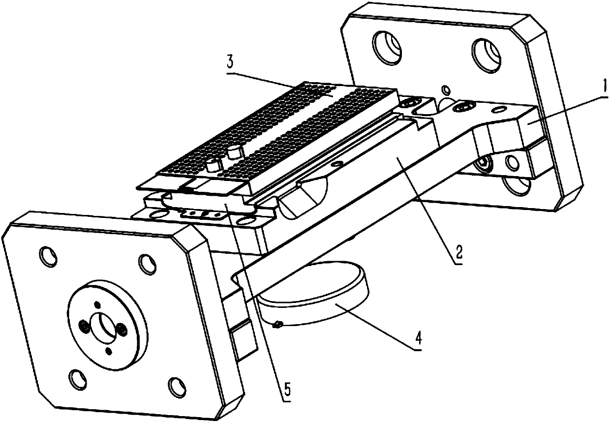
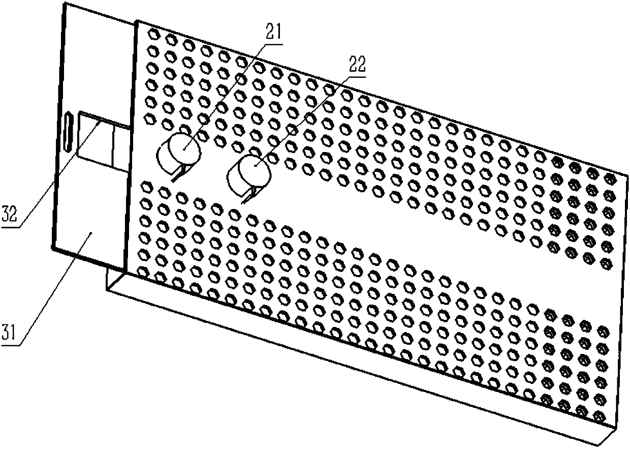
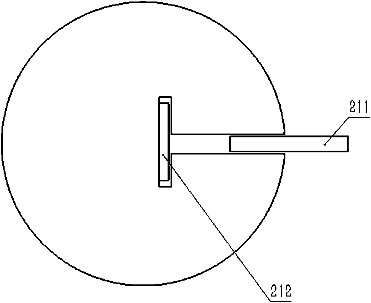
[0033] Such as Figure 1-3 As shown, a mobile phone shell magnetic clamping fixture includes: a base 1; a positioning plate 2, which is fixedly connected to the base 1, and at least a first positioning rod 21 and a first positioning rod 21 are fixedly connected to the positioning plate 2. The second positioning rod 22, the upper surface of the positioning plate 2 conforms to the shape of the mobile phone case to be processed, and the horizontal connection line direction of the first positioning rod 21 and the second positioning rod 22 is parallel to the length direction of the positioning plate 2; Pressing plate 3, the main body of which adopts a honeycomb structure, the honeycomb holes on the upper surface of the pressing plate 3 are open, the honeycomb holes on the lower surface of the pressing plate 3 are closed, the upper part of the side wall of the pressing plate 3 is provided with a first groove, and the first groove The honeycomb hole in the pressing plate is traversed...

Embodiment 2

[0040] The mobile phone shell magnetic clamping fixture also includes a rigid guard plate 5 installed between the pressing plate 3 and the positioning plate 2 . The distance between the lower surface of the first permanent magnet block 211 and the upper surface of the positioning plate 2 is equal to the sum of the thickness of the mobile phone case, the thickness of the rigid guard plate 5 and the thickness of the pressure plate 3 . The rigid guard 5 is used to increase the rigidity of the mobile phone case, so that the tool can use greater power and speed when processing the mobile phone case, thereby improving production efficiency. Due to the increase of the rigid guard plate 5 in this embodiment, the height of the corresponding lower surface of the first permanent magnet block 211 from the upper surface of the positioning plate should also be adjusted correspondingly to the thickness of the mobile phone case and the rigid guard plate 5. The sum of the thickness and the thi...


PUM


Abstract

The invention relates to a mobile phone shell magnetic clamping fixture. The mobile phone shell magnetic clamping fixture comprises a base, a positioning plate, a pressing plate, a soft magnetic filler and a magnetic field generator, wherein the positioning plate is at least fixedly connected with a first positioning rod and a second positioning rod, and the upper surface of the positioning plateis matched with the shape of a mobile phone shell to be machined; a main body of the pressing plate adopts a honeycomb structure, honeycomb holes in the upper surface of the pressing plate are open, honeycomb holes in the lower surface of the pressing plate are closed, a first groove is formed in the upper part of the side wall of the pressing plate, and the first groove transversely penetrates through the honeycomb holes; the soft magnetic filler is granular and used for filling the honeycomb holes; and the magnetic field generator is located under the base, a magnetic field produced by the magnetic field generator covers an area of the positioning plate and the pressing plate. According to the mobile phone shell magnetic clamping fixture, the mobile phone shell is clamped through magnetic force, the mobile phone shell magnetic clamping fixture is fast, convenient and efficient in cleaning, local force adjustment can be conducted on the mobile phone shell, the force size of the mobilephone shell can be wholly adjusted, and the mobile phone shell can be assembled, disassembled and locked more easily.

Description

technical field [0001] The invention relates to a clamping fixture, in particular to a magnetic force clamping fixture for a mobile phone shell. Background technique [0002] In the process of mechanical manufacturing, the device used to fix the mobile phone case to be added is called a fixture. The use of fixtures improves the efficiency and precision of mechanical manufacturing. With the development of science and technology, people's living standards continue to improve, and people's requirements are also increasingly high, which has spawned more and more manufacturing fields that require high-precision requirements. The pursuit of high-precision products is inseparable from the use of various fixtures in many occasions. [0003] In order to pursue high-precision design fixtures, the requirements for fixture details are getting higher and higher. For many special mobile phone cases or special processing requirements under special circumstances, the force requirements o...

Claims


Application Information

Patent Timeline
Patent Type & Authority Applications(China)
IPC IPC(8): B23Q3/06B23Q3/154
Inventor 郑海男
Owner 苏州海盛精密机械有限公司
Learn More