Drainage system and drainage control method
A drainage system and control method technology, applied in the direction of waterway system, sewage discharge, drainage structures, etc., can solve the problems of losing the meaning of diversion wells, rainwater and sewage diversion control is not very good, etc., to achieve a small footprint, powerful functions, The effect of reducing manpower and material resources
- Summary
- Abstract
- Description
- Claims
- Application Information
AI Technical Summary
Problems solved by technology
Method used
Image

Examples
Embodiment 1
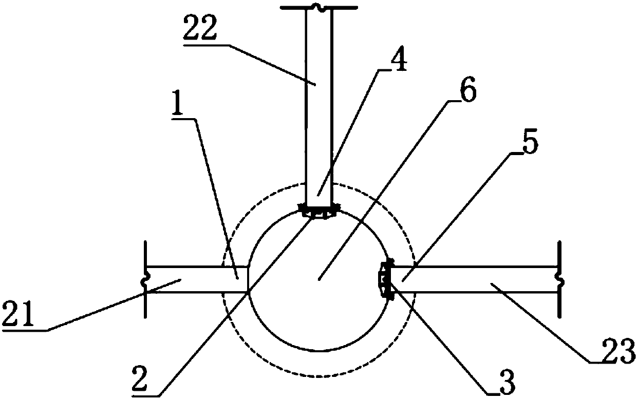
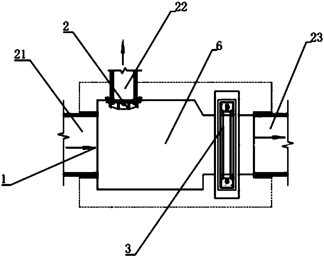
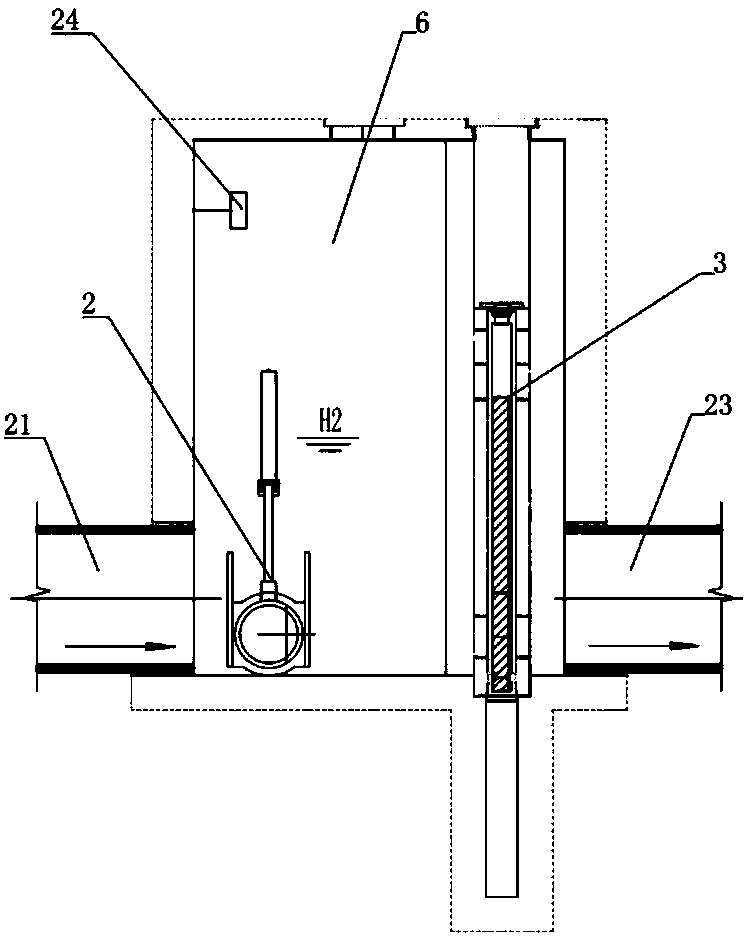
[0163] Such as Figure 1-3 As shown, the present embodiment provides a drainage system, the drainage system includes a diversion well; the diversion well includes a diversion well body 6 and three openings arranged in the diversion well body, which are respectively the water inlet 1 , the first water outlet 4 and the second water outlet 5;
[0164] The drainage system also includes a first water conservancy switch 2 and a fourth water conservancy switch 3; wherein, the first water conservancy switch 2 is provided near the first water outlet 4 for controlling the amount of water passing through the first water outlet 4; A fourth water conservancy switch 3 is provided near the second water outlet 5 for controlling the amount of water passing through the second water outlet 5;
[0165] The drainage system also includes a control system, the control system includes a monitoring device 24 and a control unit (not shown) connected to the signal; the control unit is connected to the ...
Embodiment 2
[0178] Such as Figure 4-Figure 6 A drainage system is shown, and the drainage system includes the drainage system described in Embodiment 1, and also includes a regulation and storage facility 31 .
[0179] Such as Figure 4-Figure 5 As shown, the regulation and storage facility 31 is arranged on the branch road branched from the water outlet pipe 23; at this time, the sixth hydraulic switch 32 is set on the water outlet pipe 23 pipe and at the downstream end of the branch branch of the water outlet pipe. , the sixth water conservancy switch 32 is connected with the control unit signal, and the control unit controls the opening degree of the sixth water conservancy switch 32 according to the received signal; The opening of the switch adjusts the flow direction of the water body; when the sixth water conservancy switch is in the open state, part of the water body flows through the outlet pipe and is directly discharged to the pipeline leading to the natural water body, and pa...
Embodiment 3
[0185] Such as Figure 7-Figure 10 A drainage system shown, the drainage system includes the drainage system described in Embodiment 1, and also includes an online treatment facility 41;
[0186] Such as Figure 7 As shown, the on-line treatment facility 41 is arranged on the outlet pipe; when the on-line treatment facility is arranged on the outlet pipe; the water flows into the on-line treatment facility from the inlet port of the on-line treatment facility through the outlet pipe, and after treatment, from The outlet end of the online treatment facility flows into the downstream end of the outlet pipe.
[0187] Such as Figure 8-Figure 9 As shown, the on-line treatment facility 41 is set on a branch branched from the water outlet pipeline and the terminal is merged into the water outlet pipeline; When on the branch of the road, the seventh water conservancy switch 42 is set on the outlet pipe pipeline and between the branch branch and the merge position. The seventh hyd...
PUM
 Abstract
Description
Claims
Application Information
 - R&D Engineer
- R&D Manager
- IP Professional
- Industry Leading Data Capabilities
- Powerful AI technology
- Patent DNA Extraction
Browse by: Latest US Patents, China's latest patents, Technical Efficacy Thesaurus, Application Domain, Technology Topic.
© 2024 PatSnap. All rights reserved.Legal|Privacy policy|Modern Slavery Act Transparency Statement|Sitemap