Damping base for electrical test

A shock-absorbing base, electrical test technology, applied in the direction of shock absorbers, engine bases, springs/shock absorbers, etc., can solve the problem of not being able to adjust the shock absorption amplitude, and achieve the effect of increasing practicability and increasing shock absorption amplitude.

Active Publication Date: 2018-01-19
新昌县佳良制冷配件厂
View PDF4 Cites 4 Cited by
  • Summary
  • Abstract
  • Description
  • Claims
  • Application Information

AI Technical Summary

Problems solved by technology

[0004] Aiming at the deficiencies of the prior art, the present invention provides an electric test

Method used


Image

  • Damping base for electrical test
  • Damping base for electrical test

Examples


Embodiment Construction

[0017] The following will clearly and completely describe the technical solutions in the embodiments of the present invention with reference to the accompanying drawings in the embodiments of the present invention. Obviously, the described embodiments are only some, not all, embodiments of the present invention. Based on the embodiments of the present invention, all other embodiments obtained by persons of ordinary skill in the art without making creative efforts belong to the protection scope of the present invention.

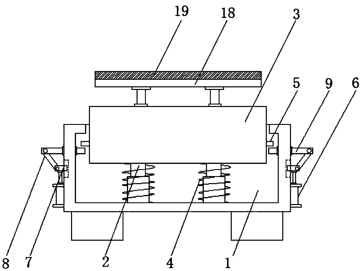
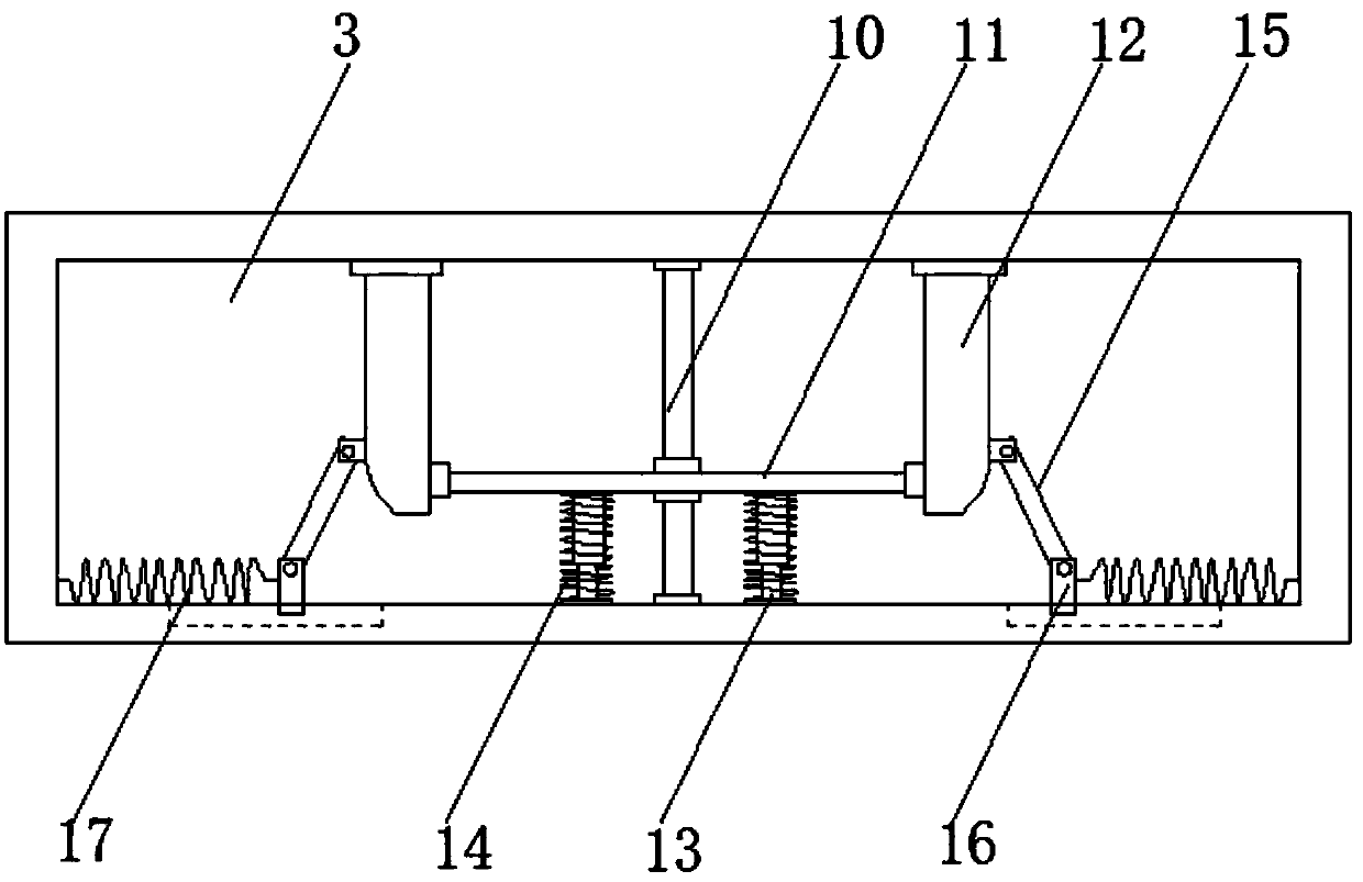
[0018] see Figure 1-2 , the present invention provides a technical solution: an electrical test shock-absorbing base, including a box body 1, the bottom of the inner cavity of the box body 1 is fixedly installed with a first telescopic sleeve 2, and the top end of the first telescopic sleeve 2 is A shock absorbing box 3 is fixedly installed, and a first spring 4 is fixedly installed on the first telescopic sleeve 2 between the bottom end of the shock absorbin...


PUM


Abstract

The invention discloses a damping base for electrical test and relates to the technical field of electrical test. The damping base for electrical test comprises a tank; a first telescopic casing pipeis fixedly installed at the bottom of an inner cavity of the tank; a damping box is fixedly installed at the top end of the first telescopic casing pipe; a first spring is fixedly installed between the bottom end of the damping box and the bottom of the inner cavity of the tank and located on the first telescopic casing pipe; clamping blocks are fixedly installed on two side walls of the damping box; hydraulic cylinders are fixedly installed on the lower portions of the outer walls of the two sides of the tank; first sliding blocks are fixedly installed at the top ends of the hydraulic cylinders and in sliding connection with the outer wall of the tank; a first rotary rod is rotationally connected with the end, away from the tank, of each first sliding block; the hydraulic cylinders drivethe first rotary rods to rotate; the first rotary rods rotate to drive clamping rods to move; and the clamping rods move to be separated from the clamping blocks. By means of the design, more dampingrequirements can be met by the device, and the practicability of the device is increased.

Description

technical field [0001] The invention relates to the technical field of electrical testing, in particular to an electrical testing shock-absorbing base. Background technique [0002] Shock absorption is a measure taken to reduce the impact of mechanical vibration on the normal operation of machines, structures or instrumentation equipment; cutting off the transmission path, which is a vibration isolation measure, can be divided into the transmission path of cutting force (positive vibration isolation) and the cutting off movement There are two ways of delivery. The former is to install a vibration isolator composed of springs and dampers between the equipment with exciting force and the foundation to reduce the force transmission rate and minimize the exciting force transmitted to the foundation, while the latter is to vibrate Install a vibration isolator between the foundation and the equipment to reduce the motion transmission rate and the response of the equipment due to ...

Claims


Application Information

Patent Timeline
IPC IPC(8): F16M5/00F16F7/00
Inventor 杨延玲
Owner 新昌县佳良制冷配件厂
Why Eureka
Try Eureka