
Efficient damping swing wall with scissor type amplifying device

An amplifying device and scissor-type technology, applied in the field of swing walls, can solve the problems of limited energy dissipation and shock absorption efficiency of swing walls, and achieve the effects of strong implementability, reduced residual deformation, and good swing amplitude

Pending Publication Date: 2022-06-24
BEIJING INST OF ARCHITECTURAL DESIGN
View PDF6 Cites 0 Cited by
  • Summary
  • Abstract
  • Description
  • Claims
  • Application Information

AI Technical Summary

Problems solved by technology

[0009] The object of the present invention is to provide a high-efficiency shock-absorbing swing wall with a scissor-type amplifying device to effectively solve the problem of limited energy dissipation and shock-absorbing efficiency of the swing wall

Method used


Image

  • Efficient damping swing wall with scissor type amplifying device
  • Efficient damping swing wall with scissor type amplifying device
  • Efficient damping swing wall with scissor type amplifying device

Examples


Embodiment 1

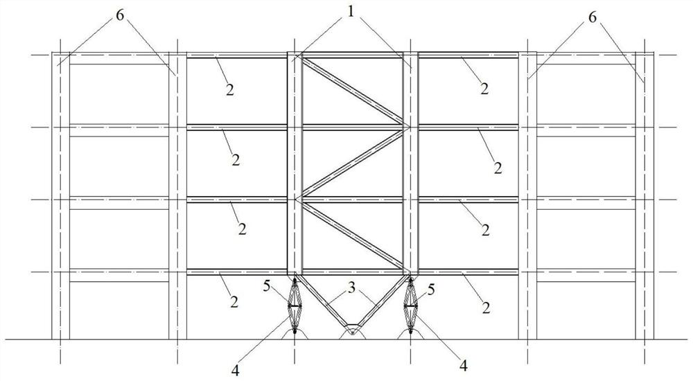
[0030] combine figure 1 and Figure 4 As shown, this embodiment provides a high-efficiency shock-absorbing rocking wall with a scissor-type amplifying device, including a rocking wall 1, a connecting steel beam 2, a steel diagonal brace 3, a scissor-type amplifying device 4 and a damper 5; wherein, the said The swinging wall is connected to the original structure 6 through the connecting steel beams, the swinging wall 1 is hingedly connected to the structural foundation through the steel diagonal braces 3 at the bottom of the structure, and the scissor-type amplifying device 4 is arranged at both ends of the lower part of the swinging wall 1 , the damper 5 is arranged in the middle part of the scissors-type amplifying device 4; .

[0031] Preferably, the scissor-type magnifying device 4 is composed of four rigid rods, and the scissors-type magnifying device 4 is hingedly connected to the structural foundation through an ear plate and a pin shaft.

[0032] Preferably, the bo...

Embodiment 2

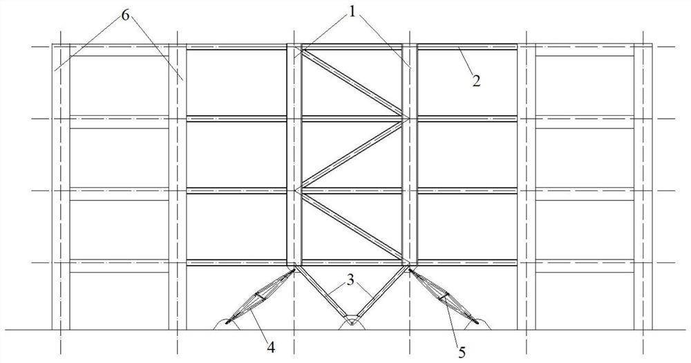
[0034] combine figure 2 and Figure 5 As shown, the difference between the second embodiment and the first embodiment is only that the bottom hinged position of the scissor-type magnifying device 4 moves outward, and is located between the original structure 6 and the rocking wall 1 .

Embodiment 3

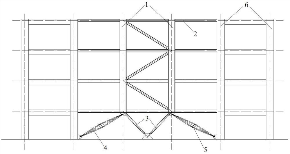
[0036] combine image 3 and Image 6 As shown, the difference between the third embodiment and the first embodiment is only that the bottom of the scissor-type magnifying device 4 is hingedly connected to the root of the original structure 6 .

[0037] This application works as follows:

[0038] The working principle of the rocking wall is to "weake" the structural system by loosening the constraints between the root and the foundation, articulating with the foundation, and "weakening" the structural system, allowing it to sway within a certain range under earthquakes, and changing the original structural deformation mode, so that the structure can finally reduce earthquakes. The effect of the reaction ensures the overall security of the structural system. In order to better control the rocking amplitude of the structure under the action of earthquake, a damper is arranged at the bottom of the rocking wall. Energy dissipation and shock absorption. The device uses the sciss...


PUM


Abstract

The invention provides an efficient damping swing wall with a scissor type amplifying device. The efficient damping swing wall comprises a swing wall body, a connecting steel beam, a steel inclined strut, the scissor type amplifying device and a damper. The swing wall is connected with an original structure through a connecting steel beam, the swing wall is hinged to a structure foundation through a steel inclined strut at the bottom layer of the structure, the scissor-type amplifying devices are arranged at the two ends of the lower portion of the swing wall, and the dampers are arranged in the middles of the scissor-type amplifying devices. The two ends of the scissor type amplifying device are hinged to the root of the swing wall and the root of the structural foundation respectively; the dampers are hinged to the two ends of the middle of the scissor-type amplifying device. The scissor-type amplifying energy dissipation device is introduced into the swing wall system, and the damping effect of the swing wall system is exerted to the maximum extent by utilizing the rotation deformation of the swing wall and amplifying the deformation or speed of the damper in the middle of the scissor-type amplifying device. Meanwhile, the device is flexible to install and simple in structure, and the problem that the swing wall and damper combined application structure is complex is successfully solved.

Description

technical field [0001] The invention relates to the field of rocking walls, in particular to a high-efficiency shock-absorbing rocking wall with a scissor-type amplifying device. Background technique [0002] As an important lateral force-resisting component, shear wall is widely used in frame-shear wall structure, shear wall structure, frame-cylinder structure. It has the advantages of high lateral stiffness and high bearing capacity, but due to its ductility Insufficient, often there will be different degrees of damage in the earthquake and it is difficult to repair, for high-rise and super high-rise buildings, this disadvantage is more obvious. Since shear walls will inevitably be damaged to a certain extent under the action of strong earthquakes, if the damage location and degree of damage can be effectively controlled, the purpose of "repairable" can be achieved. [0003] In the process of investigating the earthquake damage of previous earthquakes, the researchers fou...

Claims


Application Information

Patent Timeline
Patent Type & Authority Applications(China)
IPC IPC(8): E04B2/58E04B1/98E04H9/02
CPCE04B2/58E04B1/98E04H9/02E04H9/023E04H9/0237E04H9/024E04H9/027
Inventor 閤东东苗启松解琳琳刘谦敏程俊飞赵帆卢筱奚琦史炎升
Owner BEIJING INST OF ARCHITECTURAL DESIGN
Learn More