Evaporator core

A technology of evaporator core and core body, which is applied in the direction of evaporator/condenser, tubular element, heat exchange equipment, etc., can solve the problem that the heat absorption efficiency of the evaporator cannot be improved, the space utilization efficiency cannot be improved, and the fins cannot be changed. In order to achieve the effect of reasonable structure, good practicability, and improved heat absorption efficiency

Inactive Publication Date: 2018-01-19
TONGLING HUIYU IND CO LTD
View PDF7 Cites 8 Cited by
  • Summary
  • Abstract
  • Description
  • Claims
  • Application Information

AI Technical Summary

Problems solved by technology

[0002] At present, the fins on the core of the evaporator are all fixed on the heat-absorbing tubes, and the fins on two adjacent heat-absorbing tubes are arranged in the same way, which cannot improve the utilization efficiency of space, and the fins on this evaporator are all It is a fixe

Method used


Image

  • Evaporator core
  • Evaporator core
  • Evaporator core

Examples


Example Embodiment

[0016] The technical solutions in the embodiments of the present invention will be clearly and completely described below in conjunction with the accompanying drawings in the embodiments of the present invention. Obviously, the described embodiments are only a part of the embodiments of the present invention, rather than all the embodiments. Based on the embodiments of the present invention, all other embodiments obtained by those of ordinary skill in the art without creative work shall fall within the protection scope of the present invention.
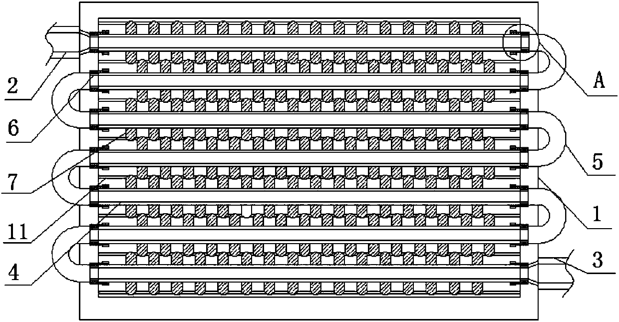
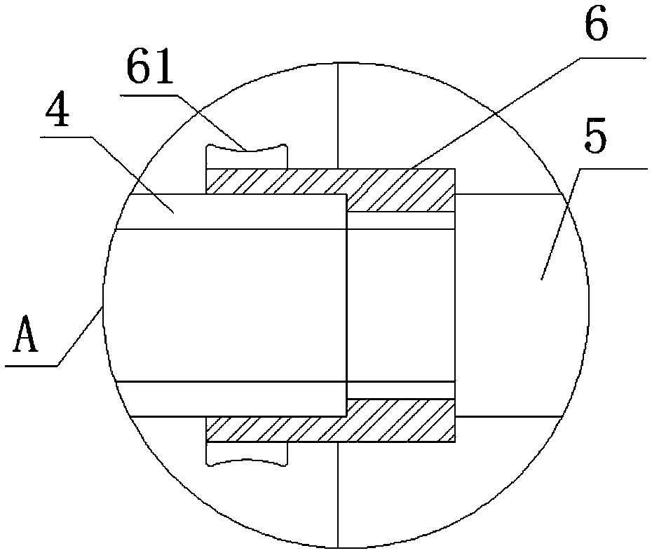
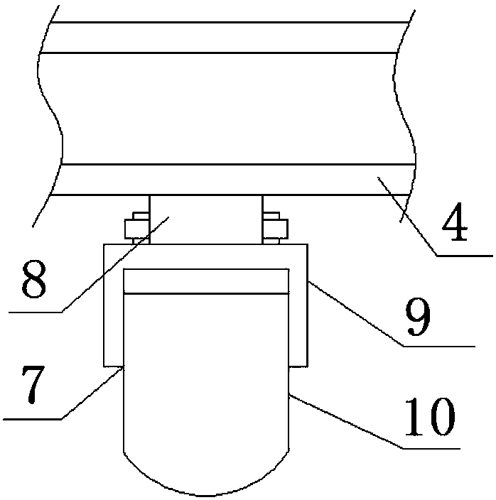
[0017] The present invention provides Figure 1-4 An evaporator core shown includes a core support frame 1, a liquid inlet pipe 2 is provided at the top of one side of the core support frame 1, and a liquid outlet pipe is provided at the bottom of the other side of the core support frame 1 3. The core support frame 1 is provided with a plurality of heat absorbing tubes 4 in the middle, and the core support frame 1 is provided with a plur...


PUM


Abstract

The invention discloses an evaporator core comprising a core supporting frame. A liquid inlet pipe is arranged at the top end of one side of the core supporting frame, and a liquid outlet pipe is arranged at the bottom of the other side of the core supporting frame. A plurality of heat absorbing pipes are arranged in the middle of the core supporting frame, and a plurality of coil pipes are arranged on the outer side of the core supporting frame. Connecting sleeves are arranged at the two ends of the heat absorbing pipes, the ends of the coil pipes are connected with the ends, away from the heat absorbing pipes, of the connecting sleeves in an attached mode, and fins are arranged at the tops and the bottoms of the heat absorbing pipes correspondingly. The multiple heat absorbing pipes arearranged on the core supporting frame, and the fins arranged in a staggered mode are arranged on the heat absorbing pipes, and thus the heat absorbing efficiency of the evaporator core is improved. Movable heat exchanging pieces on the fins are connected with fixing rods through connecting rings, limiting sleeve pieces can be separated from limiting grooves through pressing rods, the movable heatexchanging pieces can be pulled out of heat absorbing plates by moving the fixing rods, thus the areas of the fins are increased, and the heat absorbing efficiency of the evaporator core is improved.The evaporator core is reasonable in structure, simple, practical and good in practicability.

Description

technical field [0001] The invention relates to the field of evaporators, in particular to an evaporator core. Background technique [0002] At present, the fins on the core of the evaporator are all fixed on the heat-absorbing tubes, and the fins on two adjacent heat-absorbing tubes are arranged in the same way, which cannot improve the utilization efficiency of space, and the fins on this evaporator are all It is a fixed size, and the area of ​​the fins cannot be changed, that is, the heat absorption efficiency of the evaporator cannot be improved very well. At the same time, the heat absorption tubes on this evaporator are fixedly installed on the evaporator core, which is inconvenient to replace. repair. Therefore, it is necessary to invent an evaporator core to solve the above problems. Contents of the invention [0003] The purpose of the present invention is to provide an evaporator core to solve the problems raised in the background art above. [0004] In order ...

Claims


Application Information

Patent Timeline
IPC IPC(8): F25B39/02F28F1/30
Inventor 周飞吴伦保王焘徐善龙汤明明邹文冬吴光辉
Owner TONGLING HUIYU IND CO LTD
Why Eureka
Try Eureka