Solar thermal collector

A technology of solar collectors and heat exchange sleeves, applied in the field of solar energy, can solve the problems of low heat collection effect, cracked heat collection tubes, and high production costs, and achieve convenient and quick disassembly and installation of reflectors, improve heat absorption efficiency, and reduce production costs low effect

Inactive Publication Date: 2013-09-25
ZHEJIANG SHENDE NEW ENERGY
View PDF6 Cites 9 Cited by
  • Summary
  • Abstract
  • Description
  • Claims
  • Application Information

AI Technical Summary

Problems solved by technology

[0004] However, the above-mentioned solar water heater light reflection heat collection device adopts two plane mirror glass for reflection, which can only gather a small part of sunlight, and the heat gathering effect is not high. high cost
Moreover, if this kind of heat collection device is under the action of external force or special harsh environment, the heat collection tube will rupture. If one of the heat collection tubes of the heat collection device breaks, the entire heat collection device will be paralyzed and cannot continue to use

Method used


Image

  • Solar thermal collector
  • Solar thermal collector
  • Solar thermal collector

Examples


Embodiment 1

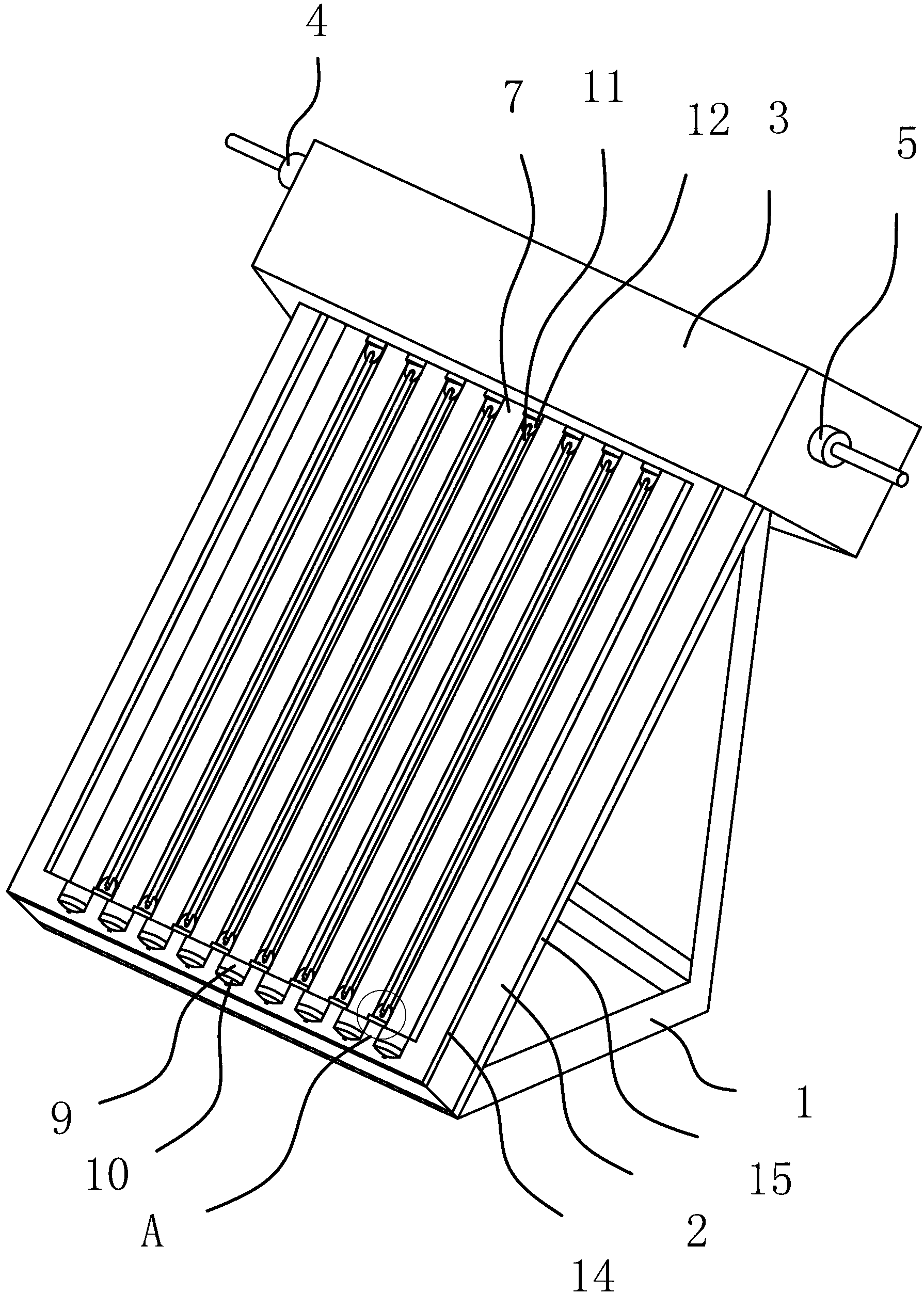
[0038] Such as figure 1 As shown, a solar heat collector includes a bracket 1 on which an installation frame 2 is obliquely fixed, a header 3 is fixed on the upper end of the installation frame 2, and a plurality of heat collecting tubes 7 are arranged inside the installation frame 2.

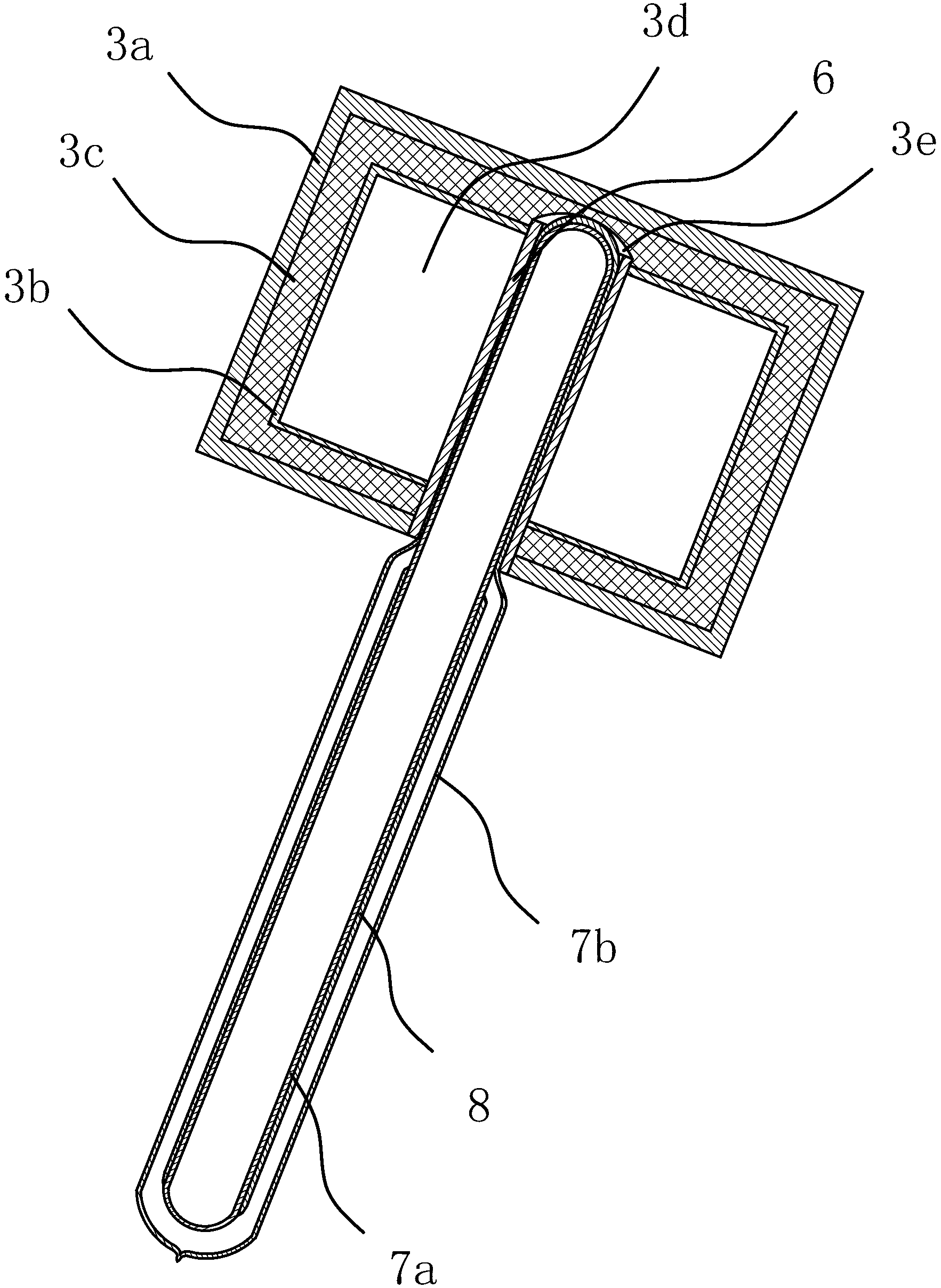
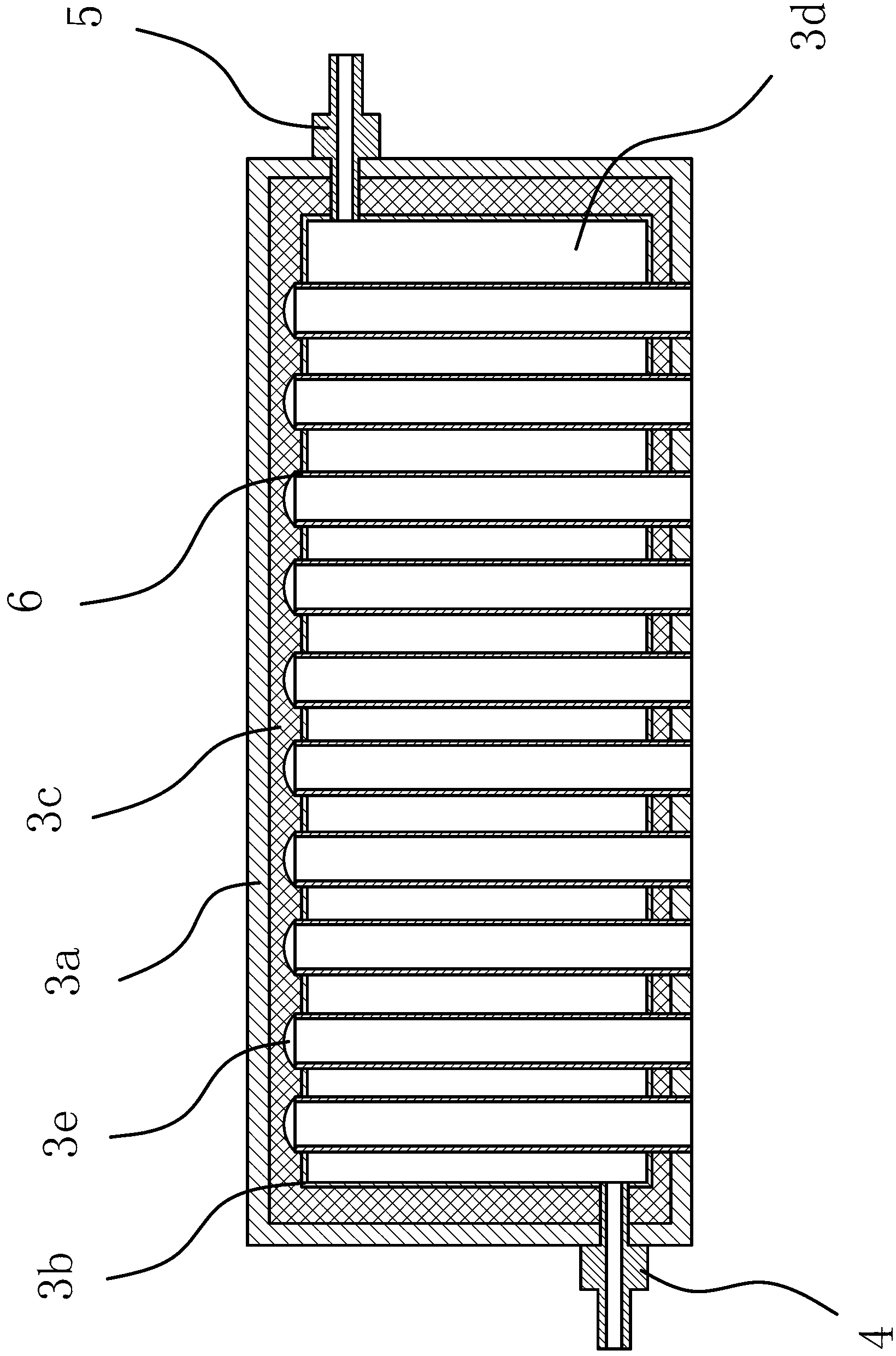
[0039] Such as figure 1 , 2 As shown in and 3, the header 3 includes an outer casing 3a, an inner container 3b is provided in the outer casing 3a, an insulating layer 3c is also provided between the inner container 3b and the outer casing 3a, and a cavity 3d is provided in the inner container 3b, and the inner container 3b is provided with a cavity 3d. The two ends of the tank 3b are respectively provided with the water inlet valve 4 and the water outlet valve 5 which are connected with the cavity 3d, and the lower side of the inner tank 3b is provided with a plurality of installation holes 1 which are connected with the cavity 3d, and the upper side of the inner tank 3b There are several mou...

Embodiment 2

[0054] The structure and principle of this embodiment are basically the same as the first embodiment, the difference is: in the first embodiment, the positioning structure one includes a positioning sleeve 9 and a positioning cap 10 fixed at the lower end of the mounting frame 2; and in this embodiment In Example 2, the positioning structure 1 includes a spring and a positioning cylinder, the lower end of the spring is fixed at the lower end of the installation frame 2, the upper end of the spring is fixed on the positioning cylinder, the lower section 72b of the outer tube body of the heat collecting tube 7 is installed in the positioning cylinder, and the outer tube The lower body section 72b abuts against the bottom plate 15 of the positioning cylinder. Press the positioning tube downward and make the spring in a compressed state, the lower section 72b of the outer tube body of the heat collecting tube 7 can be put into the positioning tube, and due to the restoring effect o...


PUM


Abstract

The invention provides a solar thermal collector and belongs to the technical field of solar energy. The technical problem that the whole thermal collector cannot continue working when any one of thermal collection tubes of an existing solar thermal collector is broken is solved by the solar thermal collector. The solar thermal collector comprises a support, a mounting frame is fixed on the support obliquely, a header is fixed at the upper end of the mounting frame and comprises a shell, a thermal insulation layer and an inner container, a cavity, a plurality of mounting holes I and a plurality of mounting holes II are formed in the inner container, the mounting holes I and the mounting holes II are communicated with the cavity, a plurality of penetration holes I and penetration holes II in communication with the mounting holes I are formed in the shell and the thermal insulation layer respectively, and a heat exchanging sleeve is arranged in each mounting hole I. A plurality of thermal collection tubes are arranged in the mounting frame, each thermal collection tube comprises an inner tube body and an outer tube body, superconductive liquid is filled in each inner tube body, and the upper section of each outer tube body is arranged in the corresponding heat exchanging sleeve. The solar thermal collector still can heat water in the header on the condition that multiple heat collection tubes are broken or fail.

Description

technical field [0001] The invention belongs to the technical field of solar energy, and relates to a heat collector, in particular to a solar heat collector. Background technique [0002] Solar energy is an inexhaustible renewable energy source for human beings, and it is also a clean energy source that does not produce any environmental pollution. With the rapid development of the economy and the continuous improvement of people's living standards, people's use of solar energy has been widely used in various solar energy products. In the heat utilization of solar energy, the key is to convert the sun's radiant energy into heat energy, which has become one of the important indicators of the development of human science and technology. Because the solar energy is relatively scattered, it must be concentrated, so the heat collector is a key part of various solar energy devices. Due to different purposes, collectors and their matching systems are divided into many types with...

Claims


Application Information

Patent Timeline
Patent Type & Authority Applications(China)
IPC IPC(8): F24J2/30F24J2/32F24J2/10F24J2/46F24S10/30F24S10/70F24S10/95F24S23/70
CPCY02E10/44
Inventor 朱肖华戴马伟沈益忠
Owner ZHEJIANG SHENDE NEW ENERGY
Why Eureka
Try Eureka