Fused-sealing type heat-pipe vacuum heat collecting pipe

A technology of vacuum heat collector and heat pipe, applied in the field of vacuum heat collector and melt-sealed heat pipe vacuum heat collector, can solve the problems of no protective measures, easy leakage, easy stress concentration, etc., so as to avoid excessive stress concentration, facilitate fixation, reduce effect of dosage

Inactive Publication Date: 2007-07-11
王军 +1
View PDF3 Cites 8 Cited by
  • Summary
  • Abstract
  • Description
  • Claims
  • Application Information

AI Technical Summary

Problems solved by technology

[0004] However, practice has proved that the above-mentioned improvement not only has a complicated process structure under high-temperature conditions such as solar thermal power generation, but also has the following shortcomings: 1. It is difficult for the melting and sealing parts to withstand high temperatures above 250 ° C, and the melting and sealing parts are directly damaged during use. Exposure to sunlight, without necessary protective measure...

Method used


Image

  • Fused-sealing type heat-pipe vacuum heat collecting pipe
  • Fused-sealing type heat-pipe vacuum heat collecting pipe
  • Fused-sealing type heat-pipe vacuum heat collecting pipe

Examples


Embodiment 1

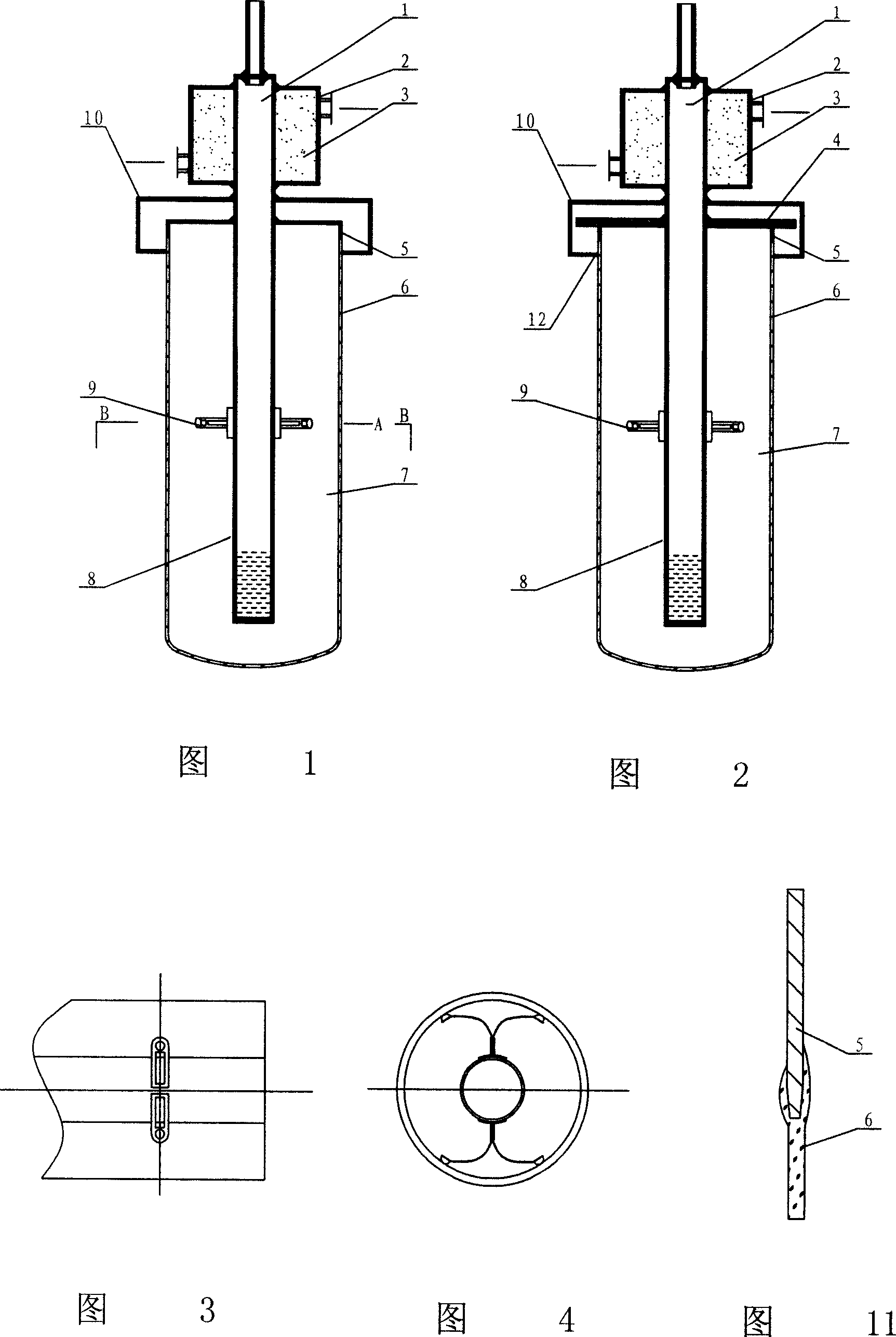
[0027] The fusion-sealed heat pipe vacuum heat collection tube of this embodiment is shown in Figure 1 , a glass outer tube 6 with one end closed is equipped with a heat pipe 1 whose lower surface is coated with a sunlight-absorbing coating 8 . The upper part of the heat pipe is sealed and welded with a cooling jacket 2 with an inlet and an outlet. The middle part of the heat pipe is welded and airtightly connected with the glass outer nozzle through Kovar 5 with flanging. A vacuum cavity 7 is formed between the glass outer tube 6 and the heat pipe 1 . The heat pipe section above the Kovar alloy fixes the upper plate of the protective cover 10, and the outer glass tube 6 cooperates with the lower plate of the protective cover. Seamed hood.

[0028] In order to eliminate the stress of thermal deformation difference on the sealing joint, the lower part of the heat pipe is equipped with a self-centering support, as shown in Figure 3 and Figure 4. There are two sets of V-shaped...

Embodiment 2

[0032] The fusion-sealed heat pipe vacuum heat collection tube of this embodiment is shown in Figure 2, and its structure is basically the same as that of Embodiment 1. The difference is that the middle part of the heat pipe 1 is inserted into the center hole of the metal flange 4 for sealing and welding. One end of the Kovar alloy ring 5 is sealed and welded to the end face near the periphery of the flange, and the other end of the Kovar alloy ring 5 and the glass outer nozzle form a plug-in fusion seal connection structure shown in FIG. 11 . In this way, the sealing effect is better, the connection strength is higher, the amount of Kovar alloy can be reduced, and at the same time, it is beneficial to the fixing of the heat collecting tube in the future system application.

[0033] In addition, the glass outer tube 6 cooperates with the inner opening of the lower plate of the protective cover to be inlaid with a bezel 12 made of heat-insulating material, so it can directly con...

Embodiment 3

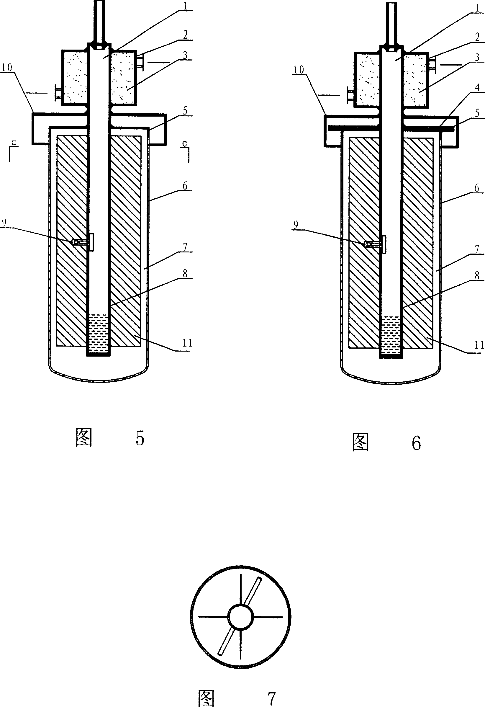
[0035] The fusion-sealed heat pipe vacuum heat collection tube of this embodiment is shown in Figure 5, and the structure is basically the same as that of Embodiment 1, the difference is that the cross-shaped fin 11 with cross-section as shown in Figure 7 is welded on the bottom of the heat pipe (of course it can also be It is a glyph fin), so it is more conducive to absorbing sunlight.


PUM


Abstract

The invention relates to a vacuum collector tube with sealing heat pipe, belonging to solar heat utilization technology area. The collector tube comprises glass outer tube and heat pipe. Upper-middle part of heat pipe inserts in the central hole of metal flange plate and is welded in sealing. Cooling jacket with water inlet and outlet ports are welded at the upper in sealing. Kovar alloy ring is welded with glass outer pipe port in sealing round the metal flange plate. Vacuum cavity is formed between glass outer tube and hot tube. Protective cover for covering the sealing connection seam is set on the hot pipe. It is provided with simple structure and feasible producing process. All sealing connection seams can not be irradiated by sun light directly. So overhigh temperature can be avoided. Fitting suit between protective cover and glass outer pipe can take the effect of assistant support and over-collection of stress at the sealing welding seam is avoided. It is especially applied in middle-high large specification vacuum collector tube with sealing heat pipe.

Description

technical field [0001] The invention relates to a vacuum heat collecting tube, in particular to a fusion-sealed heat pipe vacuum heat collecting tube working at relatively high temperature, which belongs to the technical field of solar heat utilization. Background technique [0002] The vacuum heat collector is a core device in the field of solar thermal utilization, and its main function is to convert solar energy into heat energy. The heat pipe is a high-efficiency heat transfer element, which has the characteristics of high efficiency and good safety performance. Combining the heat pipe technology with the vacuum heat collecting tube organically, the heat pipe type metal-glass vacuum heat collecting tube can be used in medium and high temperature heat utilization places, which can improve the heat transfer and safety performance of the vacuum heat collecting tube. The expansion coefficients of metal and glass are different, so after the temperature changes, the expansion...

Claims


Application Information

Patent Timeline
IPC IPC(8): F24J2/05F24J2/32F24S10/40F24S10/95
CPCY02E10/44F24J2002/4681F24J2/055F24S10/45F24S2025/6013
Inventor 王军张耀明孙利国陈强刘晓晖
Owner 王军
Why Eureka
Try Eureka