Center contact element, connector and crimping end structure of center contact element of connector

A technology of central contacts and connectors, which is applied in the direction of contact parts, two-part connection devices, connections, etc., can solve problems such as radio frequency transmission failure, substrate damage, etc., and achieve the effects of avoiding excessive stress concentration, reducing pressure, and ensuring integrity

Active Publication Date: 2022-01-25
SOUTHWEST CHINA RES INST OF ELECTRONICS EQUIP
View PDF21 Cites 0 Cited by
  • Summary
  • Abstract
  • Description
  • Claims
  • Application Information

AI Technical Summary

Problems solved by technology

[0013] The present invention aims to provide a central contact piece, a connector and a crimping end structure of the connector central contact piece, to solve the problems caused by the crimping between the central contact piece of the connector and the base material with low strength and easy creep in the prior art. Excessive pressure at the crimping point can easily lead to damage to the substrate and failure of radio frequency transmission

Method used


Image

  • Center contact element, connector and crimping end structure of center contact element of connector
  • Center contact element, connector and crimping end structure of center contact element of connector
  • Center contact element, connector and crimping end structure of center contact element of connector

Examples


Embodiment 1

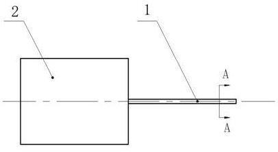
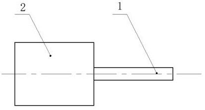
[0073] Such as Figure 8-Figure 10 As shown, this embodiment provides a connector, which includes a connector housing 2 on which a central contact 1 is connected.

[0074] The central contact piece 1 is a strip structure, the central contact piece 1 includes a straight section and an arc section, the straight section and the arc section are integrated, and the straight section and the arc section are smooth In transition, the edges of the ends of the arc segments are rounded, and the ends of the straight segments are fixedly connected to the connector housing 2 .

[0075] The arc section of the central contact 1 under pressure can form a surface contact with the substrate, which is used to disperse the pressure at the crimping part with the substrate, reduce the pressure, and protect the substrate.

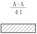
[0076] The cross-section of the central contact is rectangular, the width H of the rectangle is 0.1mm~1mm, the length L is 0.2mm~5mm, the radius R of the arc segment is 0.5mm~10m...

Embodiment 2

[0083] Such as Figure 16-Figure 17 As shown, this embodiment provides a crimping end structure of a central contact of a connector, including the connector described in Embodiment 1 and a high-frequency printed board 3 .

[0084] The connector includes an installation cavity 5 and a connector housing 2, the installation cavity 5 is provided with a connector insulating medium 6, and the connector housing 2 is connected to the installation cavity by connector mounting screws 7 On the body 5, the central contact piece 1 is connected to the connector housing 2.

[0085] The high-frequency printed board 3 is provided with a stripline or a microstrip line 4 .

[0086] Wherein, the central contact 1 is located directly above the stripline or microstrip 4 , and the central contact 1 can form surface contact with the stripline or microstrip 4 under pressure.

[0087] Such as Figure 18-Figure 20 As shown, in this embodiment, the connector housing 2 is an SMP connector housing;

[...

Embodiment 3

[0091] The difference between this embodiment and embodiment 2 is: as Figure 21-Figure 23 As shown, the connector housing 2 is an SMA type connector housing;

[0092] The width H of the cross section of the central contact 1 is 0.35 mm, the length L is 1.2 mm, the radius R of the arc segment is 1.2 mm, and the radius of the edge rounding is 0.1 mm.

[0093] The material of the central contact piece 1 is beryllium bronze, and the coating is nickel-plated on the bottom layer and gold-plated on the surface layer.


PUM


Abstract

The invention relates to the technical field of electric connectors, aims to solve the problems that in the prior art, when a connector center contact piece is in compression joint with a base material which is low in strength and prone to creeping, the base material is prone to damage and radio frequency transmission fails due to the fact that the pressure intensity at the compression joint position is too large, and provides a center contact piece, a connector and a connector center contact piece compression joint end structure. The center contact piece is of a long-strip-shaped structure, the center contact piece comprises a straight section and an arc section, the straight section and the arc section are of an integrated structure, and when the center contact piece is pressed, the arc section can be in surface contact with the base material. The beneficial effects of the invention are that: during crimping and service, the end of the central contact element can always form surface contact with the strip line or the microstrip line, and the pressure is decomposed and the pressure intensity is reduced due to the action of the arc, so that the high-frequency printed board base material and the strip line or the microstrip line on the high-frequency printed board base material are prevented from generating large shearing force in the signal transmission direction, the strip line or the microstrip line is ensured to be intact, and the reliability of radio frequency transmission is ensured.

Description

technical field [0001] The invention relates to the technical field of electrical connectors, in particular to a central contact piece, a connector and a crimping end structure of the central contact piece of the connector. Background technique [0002] In the field of electrical connectors, there are various connection methods. In the field of radio frequency connectors, N-type connectors, SMA-type connectors, SMP-type connectors, WMP-type connectors and other connection forms are used to realize coaxial transmission of radio frequency signals. When coaxial transmission is converted to stripline or microstrip transmission line (hereinafter referred to as microstrip line) transmission, the central contact of the coaxial connector and the stripline or microstrip line need to be interconnected. The common interconnection methods are Soldering, resilient contacts (such as gold tape wrap transitions), crimping, etc. [0003] In radio frequency transmission, especially in the f...

Claims


Application Information

Patent Timeline
Patent Type & Authority Applications(China)
IPC IPC(8): H01R13/02H01R24/40H01R12/55
CPCH01R13/02H01R24/40H01R12/55
Inventor 王天石王宇李鹏张义萍刘镜波李琳羊慧范民许冰张怡许柯李博刘颖杜建春徐利明刘正勇卫杰何国华
Owner SOUTHWEST CHINA RES INST OF ELECTRONICS EQUIP
Why Eureka
Try Eureka