

Extruder
A technology of extruding puffing machine and puffing chamber, which is applied in the fields of feed, food forming, food science, etc. It can solve the problems of poor adaptability to different materials and difficult adjustment of puffing chamber pressure, so as to avoid quality changes, improve the degree of ripening, and ensure The effect of quality balance
- Summary
- Abstract
- Description
- Claims
- Application Information
AI Technical Summary
Problems solved by technology
Method used
Image

Examples
Embodiment 1
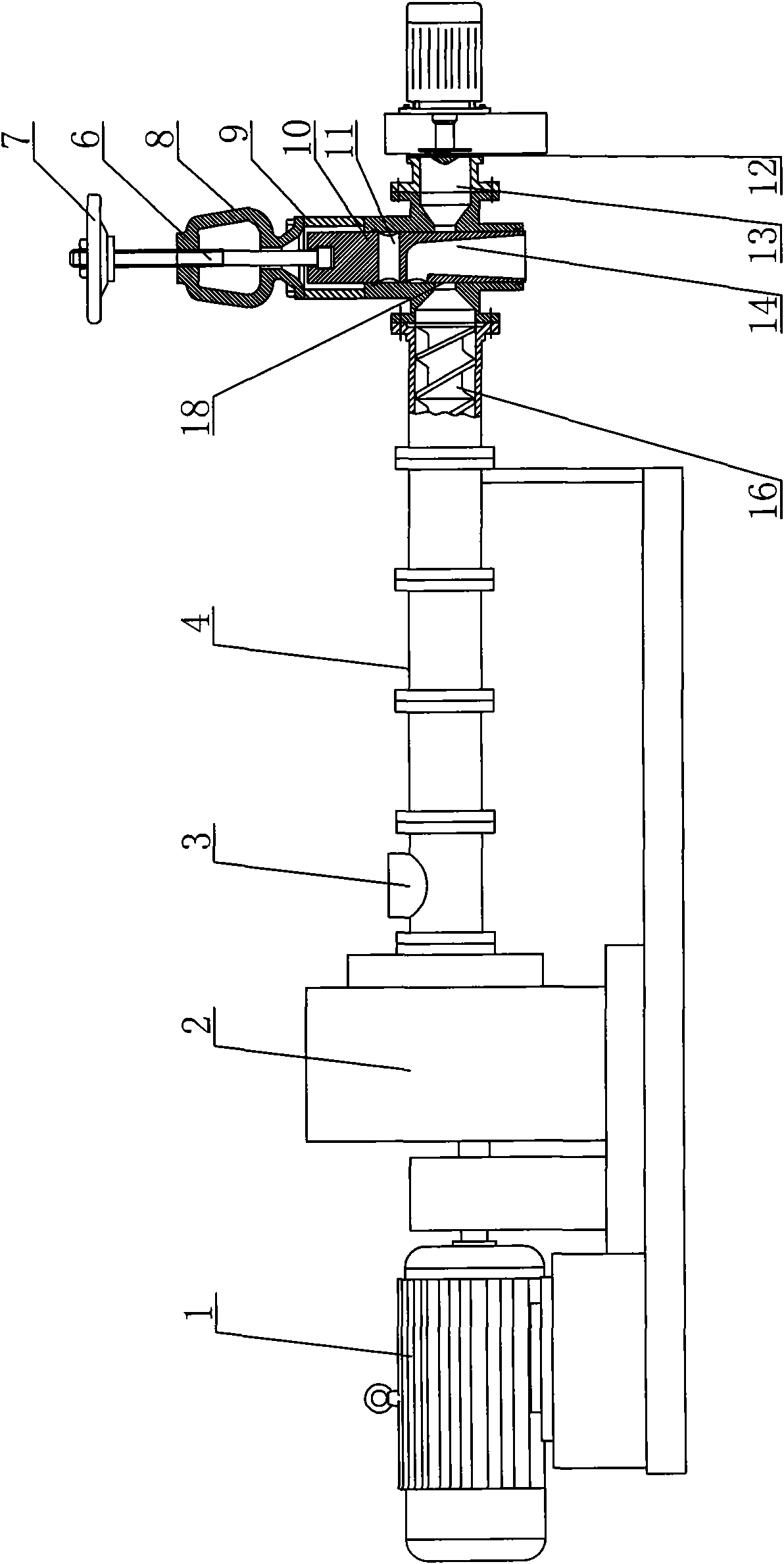
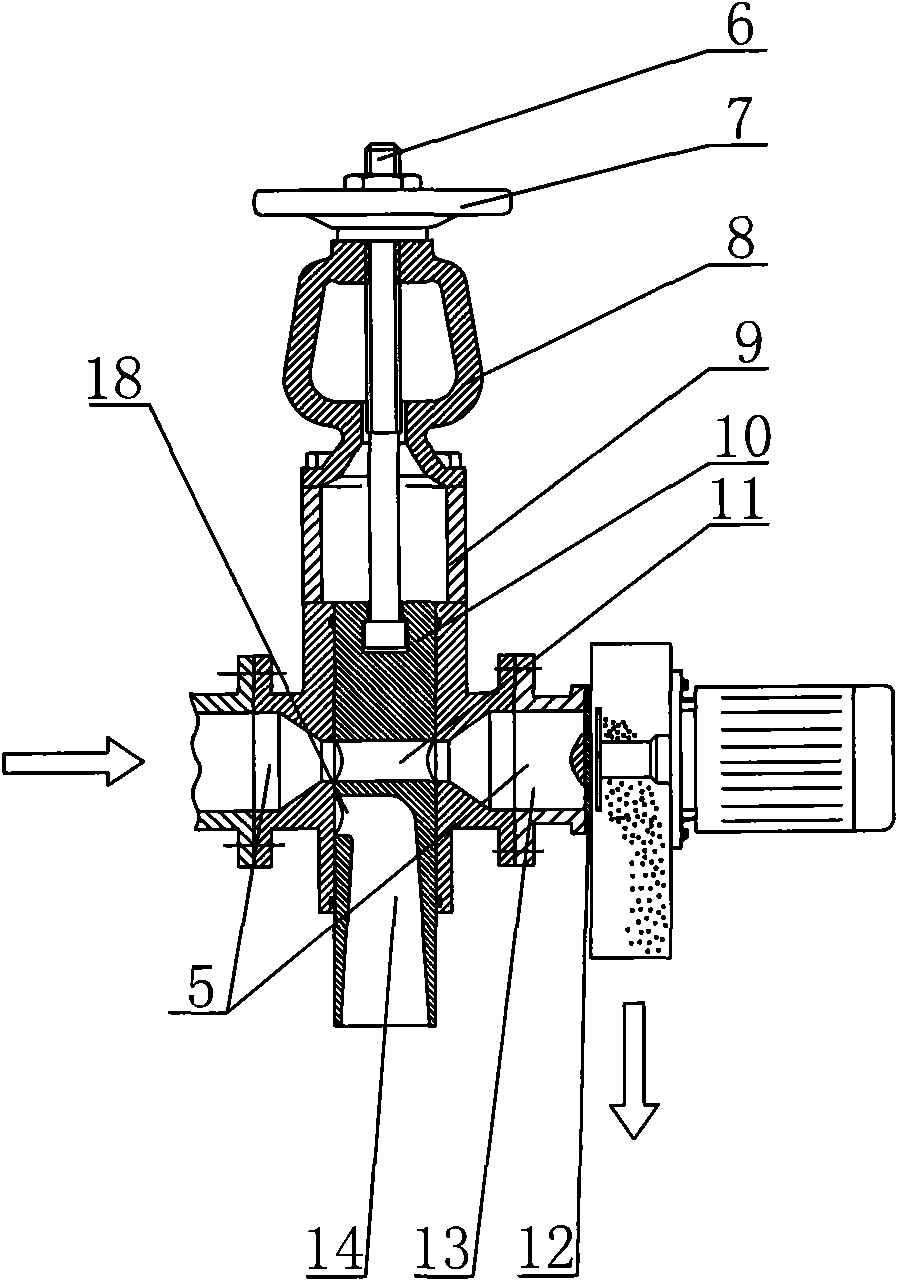
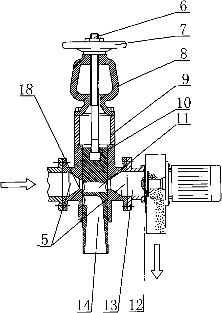
[0017] Such as figure 1 As shown, it is an extrusion puffing machine, which includes a motor 1, a transmission system 2, a feed port 3, an expansion chamber 4, and a discharge device. 4, the discharge device includes a discharge chamber 13 and a discharge template 12 arranged at the end of the discharge chamber, an extruding screw 16 is arranged in the puffing chamber 4, and the transmission system 2 is connected with the extruding screw 16 , a discharge control valve is also provided between the discharge device and the puffing chamber 4, the discharge control valve includes a valve body 9, the valve body 9 is provided with a valve chamber 5 that runs through the valve body 9 transversely, one side of the valve chamber 5 is connected to the puffing chamber The rear ends of the cavity 4 are connected, and the other side of the valve cavity 5 is connected to the discharge cavity 13; the valve body 9 is also provided with a valve core installation hole that runs through the valv...
Embodiment 2
[0023] Such as Figure 5 As shown, there are two discharge control valves, a tee 17 is provided between the rear end of the puffing chamber 4 and the discharge control valve, and the other two passages of the tee 17 are respectively connected to the discharge control valve one 15A, The discharge cavity 13 of the discharge control valve 2 15B is connected.
[0024] When working, the discharge control valve 1 15A can be in the closed state, and the discharge control valve 2 15B can be in the flow state. The material enters and is extruded from the discharge template 12 of the discharge control valve 2 15B in the flow-through state. At this time, the discharge device corresponding to the closed discharge control valve 15A can be overhauled and the discharge template 12 can be replaced; there is no need to stop for maintenance, which ensures the normal operation of the extrusion extruder, thereby realizing the efficiency of the extrusion extruder improve. It is also possible to...
PUM
 Abstract
Description
Claims
Application Information