Micro-distortion high-resolution large-visual-field optical lens

An optical lens, large field of view technology, applied in the field of optical systems, can solve the problems of low resolution and large distortion of wide-angle lenses, and achieve the effect of large field of view and small optical distortion

Active Publication Date: 2018-01-19
HUNAN DAYOPTRONICS CO LTD
View PDF4 Cites 5 Cited by
  • Summary
  • Abstract
  • Description
  • Claims
  • Application Information

AI Technical Summary

Problems solved by technology

[0002] In the environment of drones, face recognition, surveying and mapping, and high-speed cameras, the traditional wide-angle lens has large distortion and low resolution. If the combination of glass and plastic lenses is used, it will face challenges in environmental use.

Method used


Image

  • Micro-distortion high-resolution large-visual-field optical lens
  • Micro-distortion high-resolution large-visual-field optical lens
  • Micro-distortion high-resolution large-visual-field optical lens

Examples


Embodiment 1

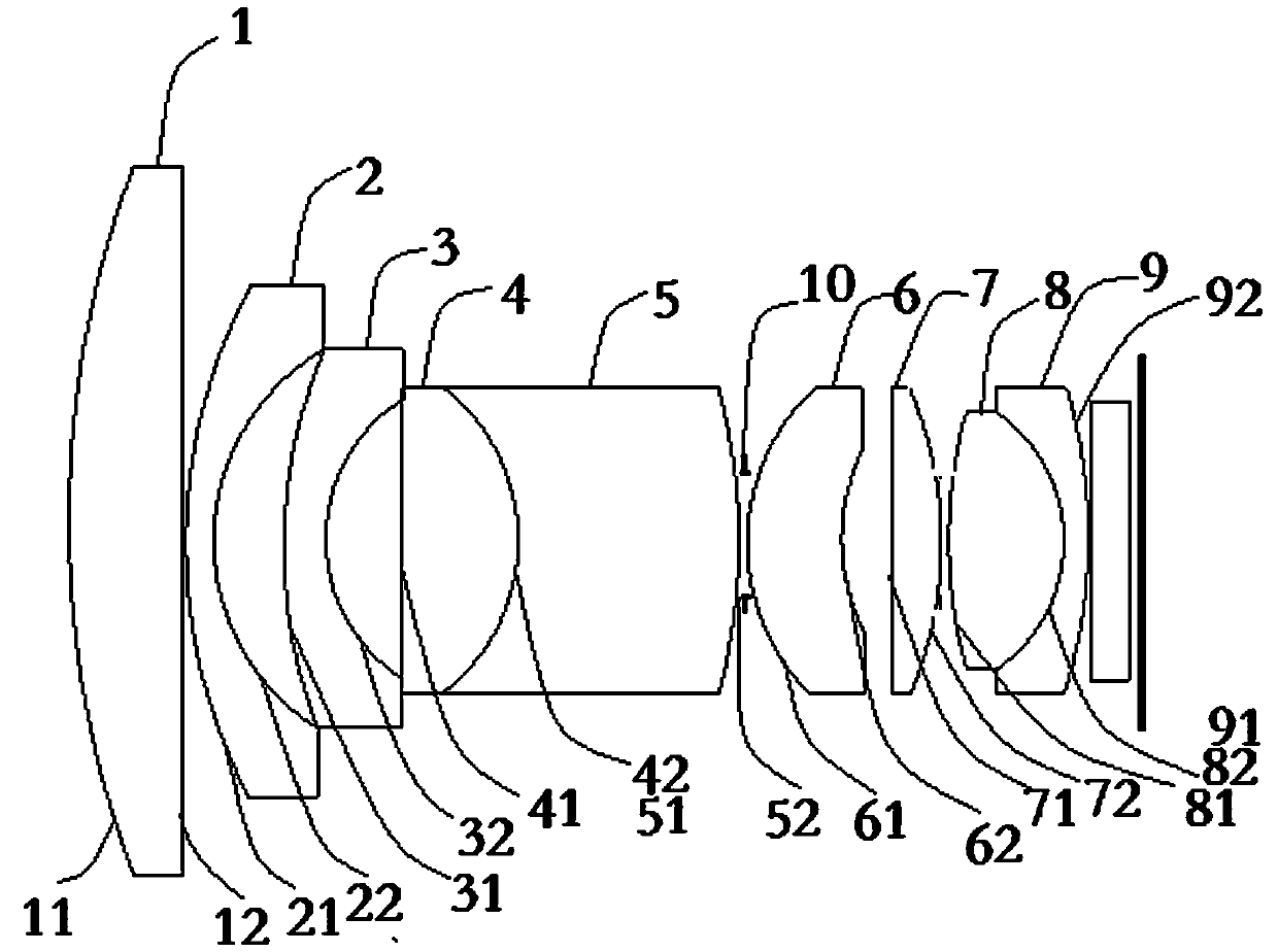
[0053] Such as figure 1 As shown, a micro-distortion high-resolution large-field-of-view optical lens provided in the embodiment of the present invention includes first lenses 1 with positive refractive power and negative refractive powers arranged in sequence along the optical axis from the object side to the image side The second lens 2 with negative refractive power, the third lens 3 with negative refractive power, the fourth lens 4 with positive refractive power, the fifth lens 5 with negative refractive power, the sixth lens 6 with positive refractive power, and the sixth lens with positive optical power A seventh lens 7 of power, an eighth lens 8 with positive power and a ninth lens 9 with negative power;

[0054] The first lens 1 includes a first surface 11 and a second surface 12, the first surface 11 is a convex surface, and the second surface 12 is a concave surface;

[0055] The second lens 2 includes a first surface 21 and a second surface 22, the first surface 21...

Embodiment 2

[0102] In this embodiment, the parameters of the optical lens are as follows: focal length f=4.3, field of view 2w=95°, and aperture number is F2.5.

[0103] Table 1:

[0104]

[0105]

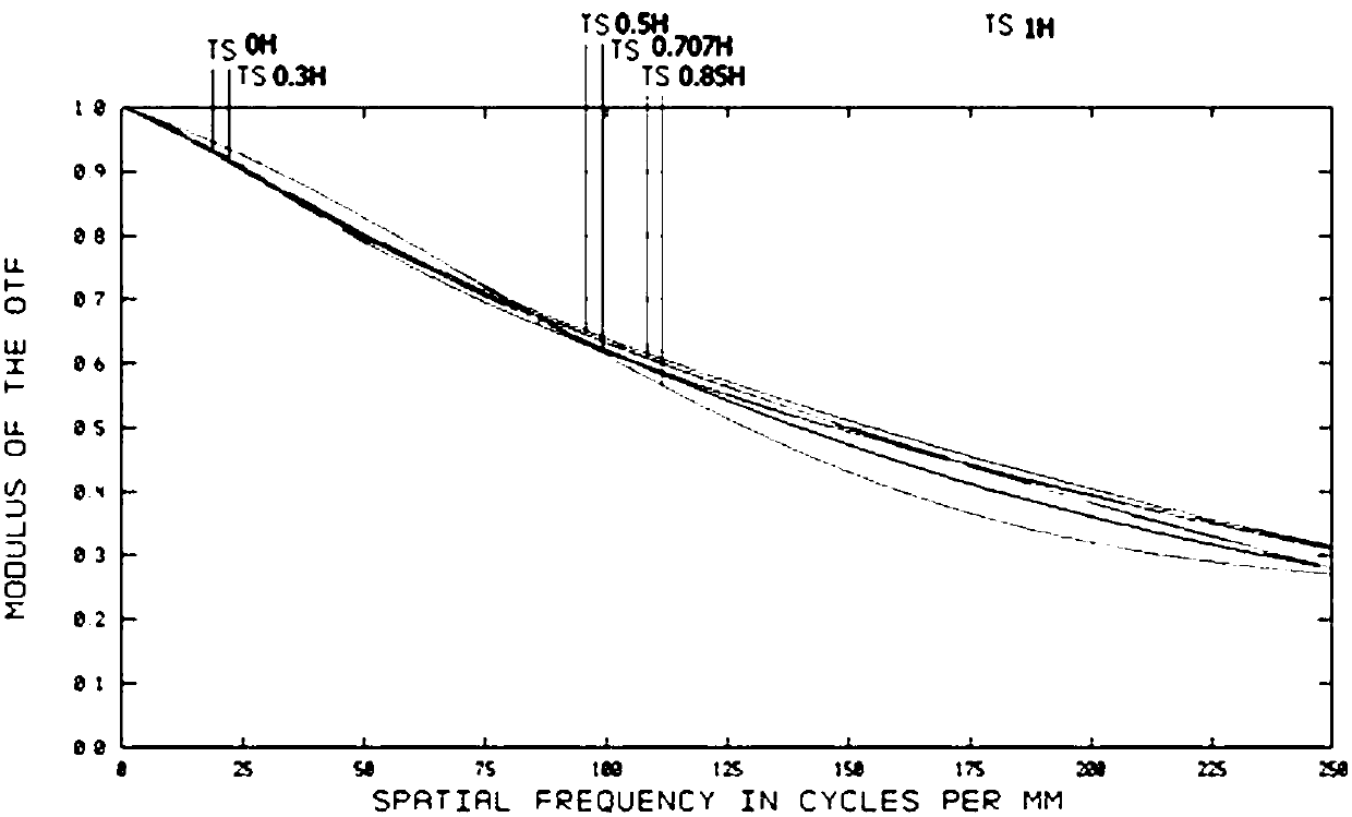
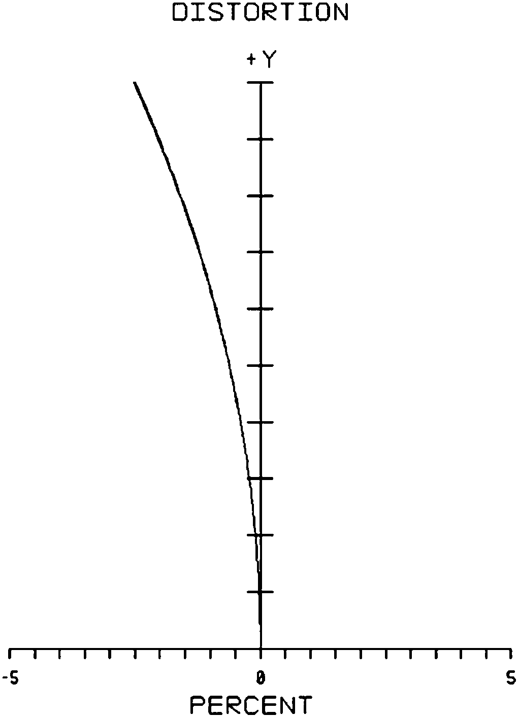
[0106] attached Figure 2~4 The optical characteristic curves of the micro-distortion high-resolution large-field optical lens in this embodiment are respectively shown, wherein:

[0107] figure 2 It is a schematic diagram of the MTF curve of the micro-distortion high-resolution large-field optical lens in this embodiment. The figure shows the comprehensive resolution level of the optical lens. It can be seen from the figure that the lens resolution can reach 4K resolution level.

[0108] image 3 It is a schematic diagram of the distortion curve, indicating the maximum absolute minimum value of the distortion under the viewing angle of this embodiment, which is less than 2.5%; it is at the level of no distortion.

[0109] Figure 4 It is a schematic diagram of the field area curve...


PUM


Abstract

The invention discloses a micro-distortion high-resolution large-visual-field optical lens. The micro-distortion high-resolution large-visual-field optical lens comprises a first lens, a second lens,a third lens, a fourth lens, a fifth lens, a sixth lens, a seventh lens, an eighth lens and a ninth lens which are sequentially arrayed from object side to image side along the optical axis. The concave surfaces of the first lens, the second lens and the third lens are falcate and face the image side, and the second lens and the third lens have negative power. The convex surface of the fourth lensis glued to the concave surface of the fifth lens and faces the image side. The convex surface of the fifth lens faces the image side. The concave surface of the sixth lens faces the image side. Theconvex surface of the seventh lens faces the image side. The convex surface of the eighth lens is glue to the concave surface of the ninth lens and faces the image side. The convex surface of the ninth lens faces the image side. A diaphragm is arranged between the fifth lens and the sixth lens. The structure of the optical lens component can be minimized, and each lens is a glass spherical lens, so that the micro-distortion high-resolution large-visual-field optical lens has the advantages of small optical distortion and large visual field.

Description

technical field [0001] The invention relates to the field of optical systems, in particular to a micro-distortion, high-resolution, and large-field optical lens. Background technique [0002] In the environment of drones, face recognition, surveying and mapping, and high-speed camera, the traditional wide-angle lens has large distortion and low resolution. If the combination of glass and plastic lenses is used, it will face challenges in environmental use. Contents of the invention [0003] In order to overcome the problems in the prior art, the object of the present invention is to provide an optical lens assembly. [0004] The present invention is realized through the following technical solutions: [0005] Provided is a micro-distortion high-resolution large-field optical lens, comprising a first lens with positive refractive power, a second lens with negative refractive power, and a negative The third lens with positive power, the fourth lens with negative power, the...

Claims


Application Information

Patent Timeline
Patent Type & Authority Applications(China)
IPC IPC(8): G02B13/00G02B13/06
Inventor 勾志勇万一兵梁小生帅皇南
Owner HUNAN DAYOPTRONICS CO LTD
Why Eureka
Try Eureka