An oil bath placement device for digestion tubes

A consistent, main-frame technology, applied to laboratory appliances, heating or cooling equipment, chemical instruments and methods, etc., can solve the problems of bursting of digestion tubes and poor safety in use, and achieve improved safety in use, convenient cleaning, and ventilation good effect

Active Publication Date: 2019-10-25
GUIZHOU UNIV
View PDF7 Cites 0 Cited by
  • Summary
  • Abstract
  • Description
  • Claims
  • Application Information

AI Technical Summary

Problems solved by technology

[0002] In the existing oil bath device, when using the digestion tube oil bath, the digestion tube is usually placed in the placement frame, and the placement frame is placed in the oil bath device for oil bath, but the digestion tube will touch the bottom of the oil bath device, The risk of bursting of the digestion tube may occur due to excessive local temperature, and the safety of use is poor

Method used


Image

  • An oil bath placement device for digestion tubes
  • An oil bath placement device for digestion tubes

Examples


Embodiment 1

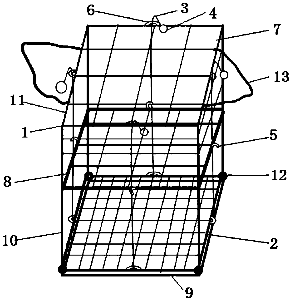
[0013] Embodiment 1: as figure 1 As shown, a device for placing an oil bath for digestion and digestion tubes includes a main frame 1 with an open lower end, and a small grid chassis 2 consistent with the main frame 1 is placed inside the main frame 1, and the small grid chassis 2 can be connected up and down movably On the main frame 1, the four sides of the small grid chassis 2 are connected with four stay ropes 3, and the other end of each stay rope 3 passes through the buckle 6 on the top of the main frame 1 and is connected with a hanging ring 4, after the hanging ring 4 moves Can be hooked to the hook 5, the hook 5 is fixedly installed on the middle and upper part of the main frame 1, the top of the main frame 1 is provided with a large grid plate 7, and the small grid chassis 2 includes a square frame and a mesh surface with small mesh holes in the frame , the mesh aperture is smaller than the diameter of the digestion pipe, the mesh set by the large mesh pan 7 is large...

Embodiment 2

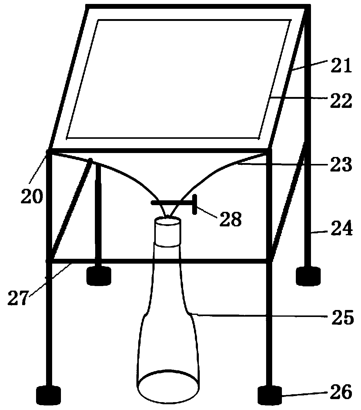
[0018] Embodiment 2: the oil recovery device of the above-mentioned digestion tube oil bath placement device, such as figure 2 As shown, the oil recovery device includes a support frame 20, a funnel 23 and an oil bottle 25, the funnel 23 is fixedly installed on the support frame 20, the oil bottle 25 is placed at the liquid outlet of the funnel 23, and the support frame 20 includes a The groove-shaped tray 21 that is consistent with the frame 9 and the pillar 24 connected to the bottom of the tray 21, the bottom of the tray 21 is provided with a filter 22, the four pillars 24 are provided with a reinforcement frame 27, and the reinforcement frame 27 is located at the liquid outlet of the funnel 23 Above, the bottom end of each pillar 24 is connected with an anti-skid rubber block 26 , and the liquid outlet of the funnel 23 is provided with a valve 28 .

[0019] After the oil bath of the digestion tube, take it out together with the placement device and place it on the oil rec...


PUM


Abstract

The invention discloses a digestion tube oil-bath placing device. The digestion tube oil-bath placing device comprises a main body framework with an opening in lower end, wherein a small grid chassiswhich is consistent with the main body framework is arranged in the main body framework; the small grid chassis can be movably connected onto the main body framework up and down; the side surface of the small grid chassis is connected with a pull rope; the other end of the pull rod passes through a buckling ring on the top of the main body framework and then is connected with a hanging ring; aftermoving, the hanging ring can be hung on a hanger; the hanger is fixedly mounted on the middle upper part of the main body framework; the top of the main body framework is equipped with a large grid chassis. The digestion tube oil-bath placing device can prevent the bottom of a digestion tube from being in contact with the bottom of an oil bath, and increases heating temperature uniformly; when boiling reagents such as sulfuric acid are added into the digestion tube, blasting caused by uneven heating is avoided, so that using safety is greatly improved; a lifting device which consists of the pull rope, the hanging ring, the hanger and the buckling ring is convenient and quick to operate, is simple in structure and is low in cost; the suspended digestion tube is better in ventilating effect, can quicken quick drop of oil liquid, and is convenient for cleaning the digestion tube.

Description

technical field [0001] The invention relates to a device for placing an oil bath for digestion tubes, and belongs to the technical field of oil bath equipment for digestion tubes. Background technique [0002] In the existing oil bath device, when using the digestion tube oil bath, the digestion tube is usually placed in the placement frame, and the placement frame is placed in the oil bath device for oil bath, but the digestion tube will touch the bottom of the oil bath device, There is a danger of the digestion tube bursting due to excessive local temperature, and the use safety is poor. Contents of the invention [0003] The technical problem to be solved by the present invention is to provide a device for placing an oil bath for a digestion tube to solve the above-mentioned problems in the prior art. [0004] The technical solution adopted by the present invention is: a device for placing an oil bath for digesting pipes, including a main frame with an open lower end, ...

Claims


Application Information

Patent Timeline
Patent Type & Authority Patents(China)
IPC IPC(8): B01L7/00
Inventor 焦克强段建军易香郭振杨丽石贵阳
Owner GUIZHOU UNIV
Why Eureka
Try Eureka