Rotary friction welding method

A spin welding and welding surface technology, applied in welding equipment, non-electric welding equipment, metal processing equipment, etc., can solve the problem of inconsistent welding effect on the contact surface, and achieve the effect of enhancing the welding firmness.

Active Publication Date: 2018-01-26
惠州荣德隆科技有限公司
View PDF2 Cites 0 Cited by
  • Summary
  • Abstract
  • Description
  • Claims
  • Application Information

AI Technical Summary

Problems solved by technology

[0003] In order to solve the problem of inconsistency in the welding effect of the contact surface caused by the difference in the linear speed of the rotating friction welding parts, the present invention provides a rotating friction welding method to achieve a firm connection of the welding parts

Method used


Image

  • Rotary friction welding method
  • Rotary friction welding method
  • Rotary friction welding method

Examples


Embodiment Construction

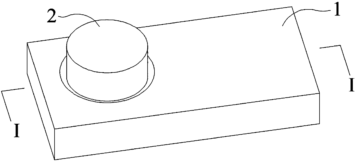
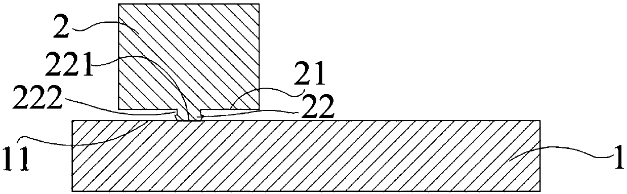
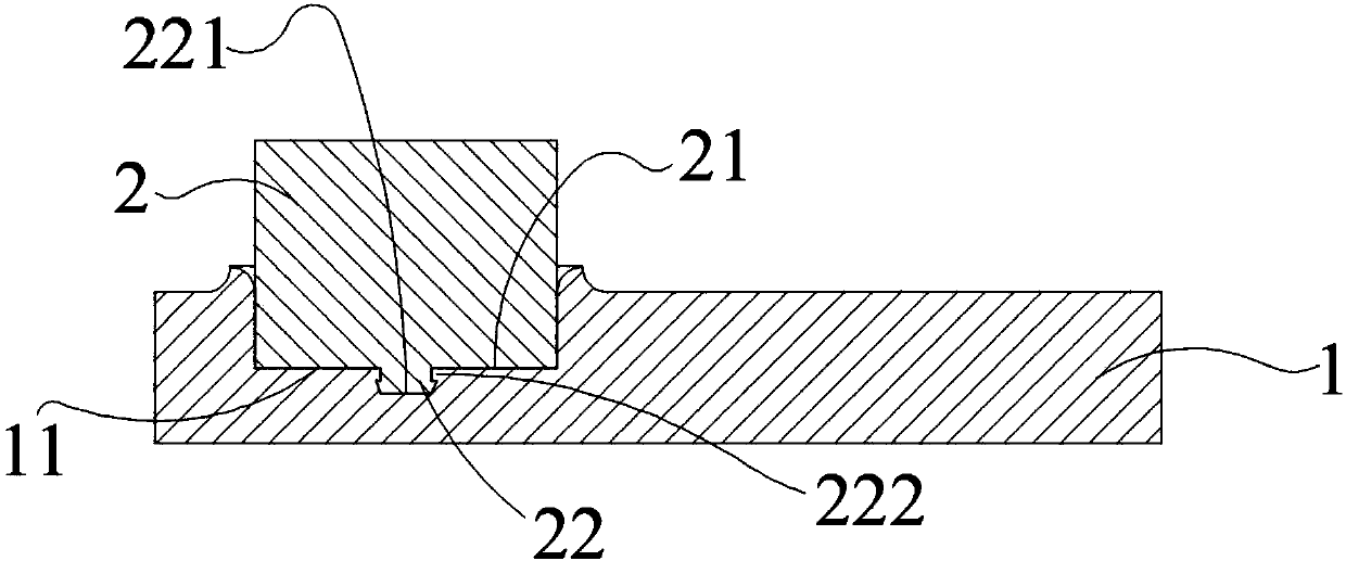
[0012] A rotary friction welding method, the main process of which is: providing a first workpiece 1 and a second workpiece 2, the first workpiece 1 is made of aluminum material, and the second workpiece 2 is a cylindrical copper material; the first workpiece is contacted The surface 11 is processed as a plane; the second workpiece bottom surface 21 is arranged with a step column 22, and the step column 22 has a groove 222 near the second workpiece bottom surface 21, and the step column 22 has a step column bottom surface parallel to the first workpiece welding surface 11 221; the first workpiece 1 and the second workpiece 2 are fixed; the second workpiece 2 is rotated so that the welding surface 11 of the first workpiece is in contact with the bottom surface 221 of the step column, so that the bottom surface 221 of the step column and the welding surface 11 of the first workpiece are frictionally heated, And apply pressure to squeeze the first workpiece 1 and the second workpi...


PUM


Abstract

The invention discloses a rotary friction welding method which comprises the following steps: providing a first workpiece and a second columnar workpiece; treating a weld face of the first workpiece into a plane; arranging a step column in the center of a bottom surface of the second workpiece, wherein a groove is formed in a peripheral side face, which is close to the bottom surface of the secondworkpiece, of the step column, and the step column comprises a step column bottom surface; fixing the first workpiece and the second workpiece; rotating the second workpiece, enabling the weld face of the first workpiece to be contacted with the bottom surface of the step column, enabling the bottom surface of the step column to be rubbed with the weld face of the first workpiece so as to raise the temperature, pressing and upsetting the first workpiece and the second workpiece until the bottom surface of the second workpiece is contacted with the weld face of the first workpiece, maintaininga state of rotating the second workpiece and a state of pressing the first workpiece and the second workpiece, and upsetting the bottom surface of the second workpiece and the weld face of the firstworkpiece; stopping rotating the second workpiece, stopping pressing the first workpiece and the second workpiece, and completing welding after the weld contact surface is cooled.

Description

technical field [0001] The invention relates to a friction welding method, in particular to a rotary friction welding method. Background technique [0002] Friction welding is a method of using the heat generated by the relative friction between the contact surfaces of the weldments to make the parts near the contact surfaces of the weldments enter a thermoplastic state, and pressurize the weldments to complete the welding. One of the typical welding methods is to rotate the cylindrical workpiece to make it rub against the surface of the opposite weldment to complete the welding. In this welding method, the contact surface of the weldment is flat, and the contact surface of the rotating weldment is away from the rotation The linear velocity of the part of the shaft is high, and the linear velocity of the part close to the rotating shaft is small, which leads to uneven heat between the outer periphery and the inside of the contact surface, and may cause weak or no welding ins...

Claims


Application Information

Patent Timeline
Patent Type & Authority Applications(China)
IPC IPC(8): B23K20/12
Inventor 吴少彬
Owner 惠州荣德隆科技有限公司
Why Eureka
Try Eureka