Method for collaboratively diagnosing fault of rolling bearing based on vibration signals of cartridge receiver

A rolling bearing and vibration signal technology is applied in the field of rolling bearing fault collaborative diagnosis for casing vibration signals, which can solve the problems of rolling bearing fault diagnosis interference, enhanced impact at non-bearing resonance frequency bands and aperiodic impact, etc., to achieve fault location. , the effect of reducing the false positive rate

Active Publication Date: 2018-01-26
NANJING UNIV OF AERONAUTICS & ASTRONAUTICS
View PDF3 Cites 24 Cited by
  • Summary
  • Abstract
  • Description
  • Claims
  • Application Information

AI Technical Summary

Problems solved by technology

However, minimum entropy deconvolution may also enhance shocks at non-bearing resonance frequency bands and aperiodic shocks, which can interfere with fault diagnosis of rolling bearings

Method used


Image

  • Method for collaboratively diagnosing fault of rolling bearing based on vibration signals of cartridge receiver
  • Method for collaboratively diagnosing fault of rolling bearing based on vibration signals of cartridge receiver
  • Method for collaboratively diagnosing fault of rolling bearing based on vibration signals of cartridge receiver

Examples


Embodiment Construction

[0084] Below in conjunction with accompanying drawing, technical scheme of the present invention is described in further detail:

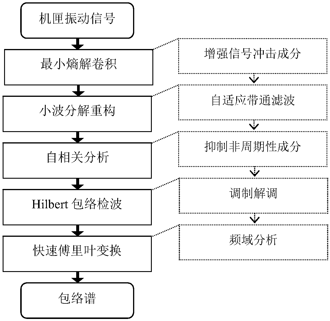
[0085] like figure 1 As shown, the present invention discloses a method for collaborative diagnosis of rolling bearing faults aimed at casing vibration signals, including the following steps:

[0086] S1: sensor arrangement and signal acquisition;

[0087] S2: Cooperative noise reduction for the vibration signal of the receiver;

[0088] S3: Envelope demodulation of noise reduction signal;

[0089] S4: Rolling bearing fault identification and location;

[0090] The step S1 specifically includes:

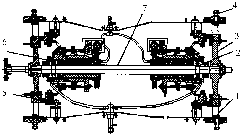
[0091] S1-1: Arrange a vibration acceleration sensor in the vertical direction of the casing;

[0092] S1-2: Set the sampling frequency of the vibration acceleration sensor to 10KHz;

[0093] S1-3: Collect the vibration acceleration signal in real time, store the vibration acceleration signal collected every 1 second as a sample, and record the spee...


PUM


Abstract

The invention discloses a method for collaboratively diagnosing the fault of a rolling bearing based on vibration signals of cartridge receiver. The method includes the following steps: S1. arranginga sensor on a cartridge receiver to acquire vibration signals; S2. based on smallest entropy convolution, enhancing the impact part of a to-be-detected signal; S3. based on wavelet transformation, extracting the resonance waveband of the rolling bearing; S4. suppressing the non-periodic part within the resonance waveband by performing autocorrelation analysis; and S5. based on Hilbert transformation envelope demodulation, positioning the fault of the rolling bearing. According to the invention, the method herein can effectively eliminate influence on signal transmission path of the rolling bearing and interference by complex background noises, highlights the spectral peaks corresponding to the feature frequency of the fault, can position the fault which causes damage to the surface of therolling bearing, and addresses difficult diagnosis, low precision and poor robustness in monitoring the fault of the rolling bearing based on vibration signals that are tested on test points of the cartridge receiver.

Description

technical field [0001] The invention relates to the field of fault diagnosis of rolling bearings, in particular to a cooperative diagnosis method for rolling bearing faults aimed at casing vibration signals. Background technique [0002] The vibration method is sensitive to early faults of rolling bearings and has been widely used in fault diagnosis of rolling bearings. However, the existing research basically takes the bearing seat signal on the bearing tester as the analysis object, and the signal is less affected by the transmission path and noise. Taking the rolling bearing of an aero-engine as an example, without changing the structure of the engine, the sensor measuring points can only be arranged on the casing, and the transmission of the vibration signal needs to go through a very complicated transmission path, coupled with the system excitation under complex working conditions There are many sources, and structural vibration noise, aerodynamic noise sources, and co...

Claims


Application Information

Patent Timeline
Patent Type & Authority Applications(China)
IPC IPC(8): G01M13/04
Inventor 陈果林桐滕春禹王云欧阳文理
Owner NANJING UNIV OF AERONAUTICS & ASTRONAUTICS
Why Eureka
Try Eureka