
Photo printer

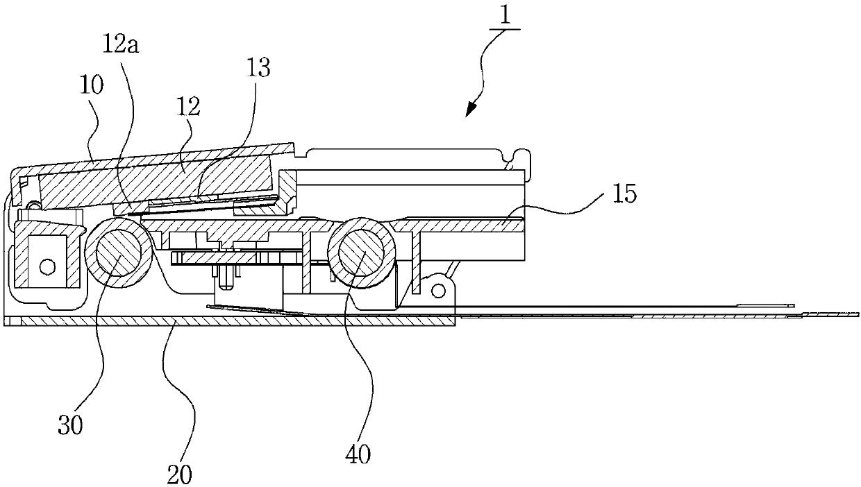
A technology of printers and photos, applied in typewriters, printing devices, printing, etc., can solve the problems of printing quality degradation, small friction between the pickup roller and paper, transmission, etc., and achieve the effect of improving printing quality, simple structure, and shrinking volume

Active Publication Date: 2018-01-30
DS GLOBAL
View PDF11 Cites 10 Cited by
  • Summary
  • Abstract
  • Description
  • Claims
  • Application Information

AI Technical Summary

Problems solved by technology

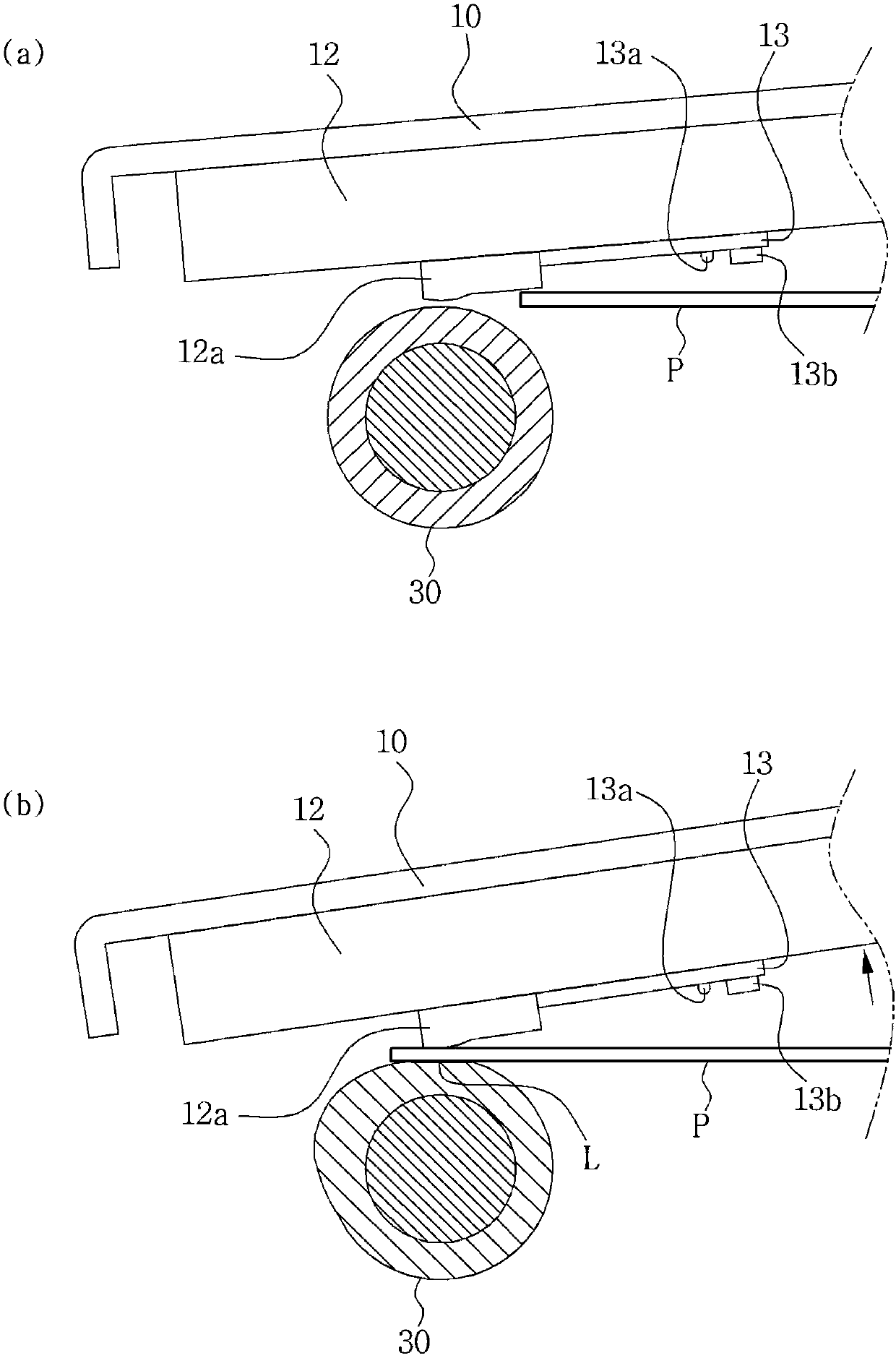
Due to the above effects, the heat of the head (12a) cannot be locally transferred to the corresponding part of the paper, but the heat is transferred to the adjacent part of the corresponding part (surface contact part, L) to realize the color, resulting in a decline in printing quality (see image 3 of (b))
[0011] Also, the frictional force between the pickup roller and the paper is small, and it often happens that the paper cannot be fed smoothly.
[0012] In addition, there is a problem that one sheet of paper needs to be fed forward by the pickup roller, but two or more sheets are fed due to static electricity between the sheets, etc.

Method used


Image

  • Photo printer
  • Photo printer
  • Photo printer

Examples


Embodiment Construction

[0048] refer to Figure 4 to Figure 6 , according to an embodiment (100) of the photo printer of the present invention, comprising: a substrate (110), a pickup roller (R1) and a platen roller (R2), a head (refer to Figure 9 '143'), swing bracket (150), pressurizing part (160).

[0049] In this embodiment, the base plate (110) is formed with a paper supply part (111) that stacks and accommodates a plurality of papers, and a lower base plate (115) extending to the front side is connected to the lower part of the base plate (110), In addition, the substrate (110) and the lower substrate (115) are formed separately for ease of manufacture, and may be integrally formed.

[0050]The pickup roller ( R1 ) is for supplying forwardly the lowermost paper among the stacked paper protruding from the bottom surface of the paper supply part ( 111 ) of the base plate ( 110 ).

[0051] In addition, a paper pressing member (120) elastically pressing paper stacked on the paper supply unit (11...


PUM


Abstract

The invention relates to a photo printer. According to the photo printer of the invention, the photo printer can offer heat at given temperature to paper showing colors to thermoinduction so that theprinter can print images or texts. The photo printer including: a base adapted to accommodate paper therein; a pickup roller protruding from the bottom of the base to feed the paper accommodated in the base forwardly; a platen roller disposed in front of the base to discharge the paper fed by the pickup roller forwardly; a head located above the platen roller to apply given heat to the paper; a swing bracket having a mounting portion formed at the front side thereof in such a manner as to be coupled to the head and coupling portions formed at the rear side thereof in such a manner as to be rotatably coupled to the base to allow the head to swing; and pressurizing means adapted to pressurize the head downwardly to allow the head to come into close contact with the paper advancing into the space between the head and the platen roller.

Description

technical field [0001] The present invention relates to a photo printer, in particular, to a photo printer that transfers heat from a head to a local part of paper to improve printing quality, and presses the entire head in the direction of a platen roller with uniform pressure. Background technique [0002] Recently, a photo printer product capable of printing digital smart cameras instantly anytime, anywhere has been developed. [0003] There are various types of such photo printers, and in particular, there is a photo printer that uses printing paper in an inkless method without requiring additional ink or ink cartridges, which can save subsequent costs. Here, the inkless method refers to a method in which a part equivalent to an ink cartridge is included in paper and a color is expressed using heat. That is, since the ink that expresses color in response to heat is deposited on the paper, an image (photograph) or text is printed by controlling the heating temperature or...

Claims


Application Information

Patent Timeline
IPC IPC(8): B41J2/32B41J3/00B65H3/06
CPCB41J2/32B41J3/36B41J11/04B41J13/02B41J13/10B41J23/02B41J29/02B41J29/38G03G15/2003
Inventor 尹熙弼
Owner DS GLOBAL
Learn More