Rearview mirror rod

A technology for rearview mirrors and rods, which is applied in the field of rearview mirror product structure, can solve the problems of increased production process difficulty and the difficulty of placing the first ring on the rearview mirror rod, so as to reduce product types, reduce development costs, The effect of simple production process

Pending Publication Date: 2018-01-30
JIANGMEN SHONGLI REARVIEW MIRROR INDAL
View PDF4 Cites 1 Cited by
  • Summary
  • Abstract
  • Description
  • Claims
  • Application Information

AI Technical Summary

Problems solved by technology

[0003] However, this makes the rearview mirror rod need to be demolded from two vertical directions, which increases the difficulty of the production process. At the same time, it is difficult for the first ring to be placed on the rearview mirror rod, and the design of the end of the rearview mirror rod connected to the iron pipe is also affected. Limits of the first circle

Method used


Image

  • Rearview mirror rod
  • Rearview mirror rod
  • Rearview mirror rod

Examples


Embodiment 1

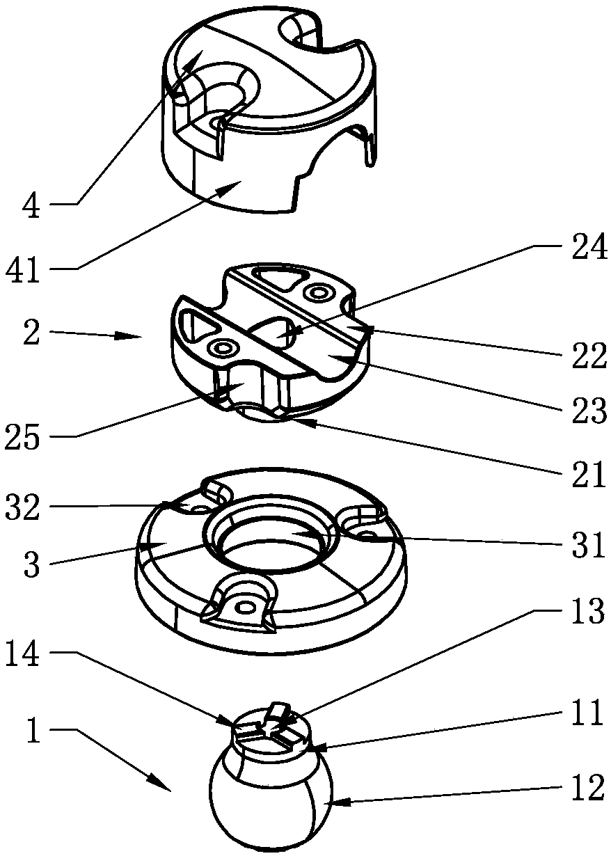
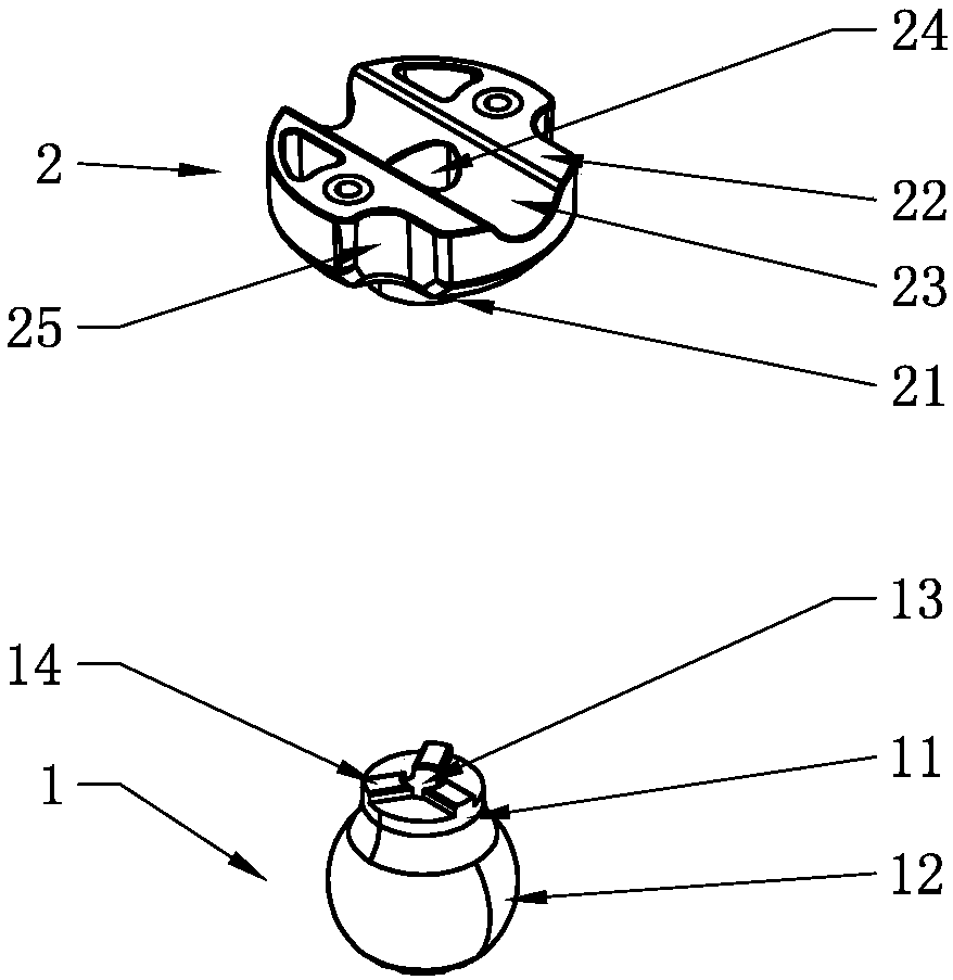
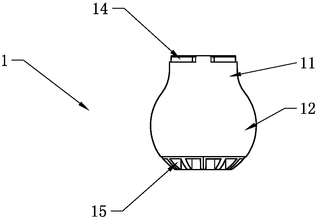
[0034] Embodiment 1: The end of the first rod 11 facing away from the first sphere 12 is provided with an external thread, and the second rod 21 is correspondingly provided with a threaded hole. External threads and threaded holes are common structures, which are not shown in the figure.

Embodiment 2

[0035] Embodiment 2: The end surface of the second rod part 21 is provided with a second through hole 24 , the second through hole 24 accommodates a second bolt, and the screw part of the second bolt is connected with the first rod part 11 .

[0036] Using the second bolt to connect the first half rod 1 and the second half rod 2 can enhance the connection strength and reduce the risk of breaking the rearview mirror rod.

[0037] As a further extension of the second embodiment, the end surface of the first rod part 11 is provided with a first protrusion 14, the first protrusion 14 is provided along the edge of the end face of the first rod part 11, and the end surface of the second rod part 21 is provided with a container Set the second recess of the first protrusion 14.

[0038] The cooperation between the first protrusion 14 and the second concave part prevents the first rod part 11 from rotating relative to the second rod part 21 , avoids loose connection, and avoids acciden...


PUM


Abstract

The invention discloses a rearview mirror rod. The rearview mirror rod comprises a first half rod and a second half rod and is characterized in that the end of the first half rod is connected with theend of the second half rod, the first half rod comprises a first rod part connected with the second half rod and a first ball connected with the first rod part, the first ball is arranged at one end,away from the second half rod, of the first rod part, the second half rod comprises a second rod part connected with the first rod part and a second mounting part connected with the second rod part,the second mounting part is located at one end, away from the first rod part, of the second rod part, and one side, away from the second rod part, of the second mounting part is provided with a secondgroove capable of accommodating an iron tube. The rearview mirror rod has the advantages that the production difficulty of the rearview mirror rod is lowered, and a first ring can conveniently sleevethe rearview mirror rod.

Description

technical field [0001] The invention relates to a rearview mirror product structure, in particular to a rearview mirror rod. Background technique [0002] In the prior art, the rearview mirror is connected to the iron pipe on the car through the rearview mirror rod, the rearview mirror rod is plastic injection molding, and the end of the rearview mirror rod near the rearview mirror is spherical and covered with a first ring , the first ring is connected with the rearview mirror, the other end of the rearview mirror rod is connected to the end cap, the end face of the rearview mirror rod is attached to the end cap, and an iron pipe is arranged between the rearview mirror rod and the end cap to facilitate the passage of The cavity, the mirror rod and the end cap are connected by bolts to clamp the iron pipe. [0003] However, this makes the rearview mirror rod need to be demolded from two vertical directions, which increases the difficulty of the production process. At the sa...

Claims


Application Information

Patent Timeline
Patent Type & Authority Applications(China)
IPC IPC(8): B60R1/02
Inventor 罗国胜罗光荣
Owner JIANGMEN SHONGLI REARVIEW MIRROR INDAL
Why Eureka
Try Eureka