Novel transmission shaft with constant-speed ball cage structure

A constant velocity spherical cage and drive shaft technology, applied in the field of drive shafts, can solve problems such as insufficient performance and stability, easy failures, and many parts, and achieve the requirements of compactness and light weight, improve overall life, and reduce product types.

Inactive Publication Date: 2012-08-22
WANXIANG QIANCHAO TRANSMISSION SHAFT +1
View PDF7 Cites 0 Cited by
  • Summary
  • Abstract
  • Description
  • Claims
  • Application Information

AI Technical Summary

Problems solved by technology

Due to the large number of parts, the cost is high, it is prone to failure, and the performance and stability are also insufficient

Method used


Image

  • Novel transmission shaft with constant-speed ball cage structure
  • Novel transmission shaft with constant-speed ball cage structure

Examples


Embodiment Construction

[0010] The present invention will be further described below in conjunction with the accompanying drawings and embodiments. While the invention will be described in conjunction with the preferred embodiments, it will be understood that it is not intended to limit the invention to the described embodiments. On the contrary, the invention is to cover alternatives, modifications and equivalents, which may be included within the scope of the invention as defined by the appended claims.

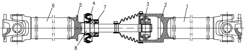
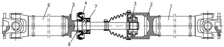
[0011] see figure 1 As shown, this new drive shaft with constant velocity ball cage structure includes front axle tube 1, cylindrical shell 2, ball cage 3, and rear axle tube 6 in sequence. The front axle tube 1 is directly welded to the cylindrical shell 2, and the cylindrical shell The other end of the shaped shell 2 is provided with a ball cage 3, and the front axle tube 1 is connected with the shaft head 5 of the ball cage 3, and the shaft head 5 is provided with an intermediate bracket 4. T...


PUM


Abstract

The invention discloses a novel transmission shaft with a constant-speed ball cage structure, which sequentially comprises a front shaft tube, a cylindrical shell, a ball cage and a rear shaft tube, wherein the front shaft tube and a shaft head of the ball cage are respectively provided with an intermediate support. The novel transmission shaft has beneficial effects that: compared with an original transmission shaft structure, an intermediate spline shaft and an intermediate flange are saved, the varieties of components can be reduced, and the management cost can be reduced; since the components and the spline pair are reduced, the failure possibility of the transmission shaft can be reduced, and the integral service life of the transmission shaft is improved; on the aspect of the dynamic balance of the transmission shaft, since one spline pair is reduced, the fit clearance is reduced, and the dynamic balance performance is improved; and a rotating diameter of the transmission shaft is much smaller than that of an original structure, and the requirements of a main machine factory on compactness of the space layout and light weight of a chassis can be satisfied.

Description

technical field [0001] The invention relates to a transmission shaft, more specifically, it relates to a novel transmission shaft with a constant velocity ball cage structure. Background technique [0002] In the prior art, the drive shaft intermediate connection belt constant velocity ball cage structure is connected by two spline pairs. The middle bracket is assembled on the middle spline shaft to support the drive shaft. The constant velocity ball cage plays the role of transmission shaft length expansion and angle compensation. effect. The specific components include an intermediate bracket, an intermediate spline shaft, an intermediate flange, a constant velocity ball cage, and a shaft head. Due to the large number of parts, the cost is high, failures are prone to occur, and performance and stability are also insufficient. Contents of the invention [0003] The purpose of the present invention is to overcome the deficiencies in the prior art and provide a novel tran...

Claims


Application Information

Patent Timeline
Patent Type & Authority Applications(China)
IPC IPC(8): F16D3/22F16D3/84
Inventor 曹向阳张军
Owner WANXIANG QIANCHAO TRANSMISSION SHAFT
Why Eureka
Try Eureka