
Conveniently-used hardware conveying basin

A hardware and convenient technology, which is applied in the direction of transportation and packaging, rigid containers, containers, etc., can solve the problems of easily damaged screw threads, increased screw collision friction, large manpower, etc., to achieve protection from bumps, reduce impact force, reduce damage effect

Inactive Publication Date: 2018-01-30
吴永强
View PDF8 Cites 0 Cited by
  • Summary
  • Abstract
  • Description
  • Claims
  • Application Information

AI Technical Summary

Problems solved by technology

[0002] At present, the pots used to hold threaded hardware tools are generally the pots purchased on the market. During the transportation of such pots, it is necessary to pile up the pots full of screws or hardware for storage or transportation. The bottom of the previous pot will be in contact with the screws in the next pot, but when transporting this kind of pot, the bumps in the transportation will cause the bottom of the previous pot to collide with the screws in the next pot and the friction will increase, which will easily damage the screws or other screws. The threads of hardware accessories lead to a relatively high scrap rate of screws and threaded hardware; and some hardware handling basins are generally made of hard materials such as metal, which are easy to cause bumps when placed, affecting the service life, and some hardware handling basins To ensure stability, it needs to be lifted from the bottom
However, there is no gap between the bottom of the existing basin and the supporting surface, and it takes a lot of effort to lift one side and carry it, which consumes a lot of manpower

Method used


Image

  • Conveniently-used hardware conveying basin
  • Conveniently-used hardware conveying basin
  • Conveniently-used hardware conveying basin

Examples


Embodiment Construction

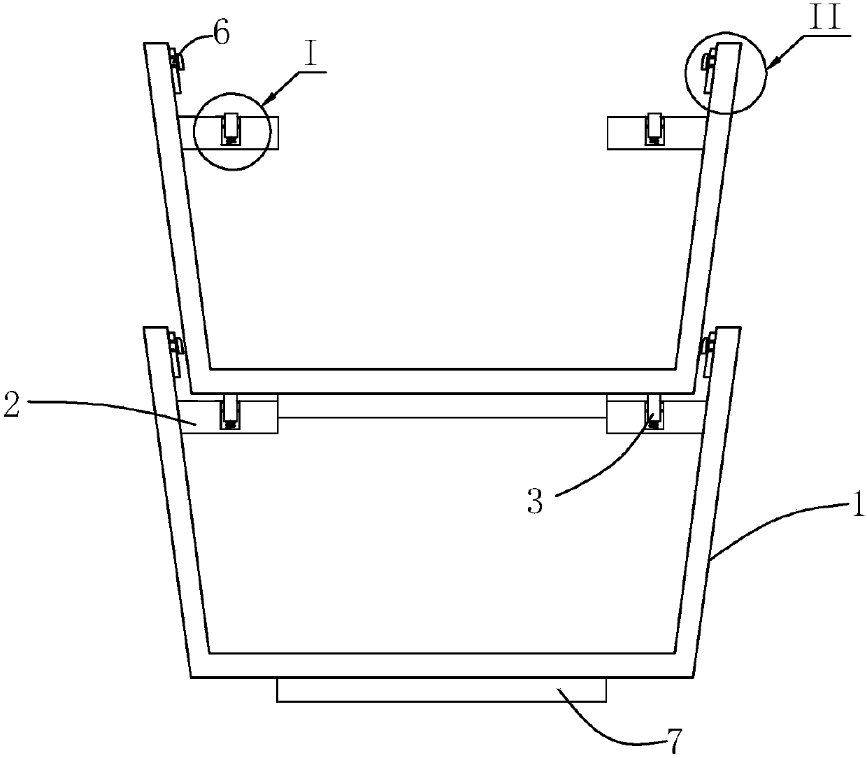
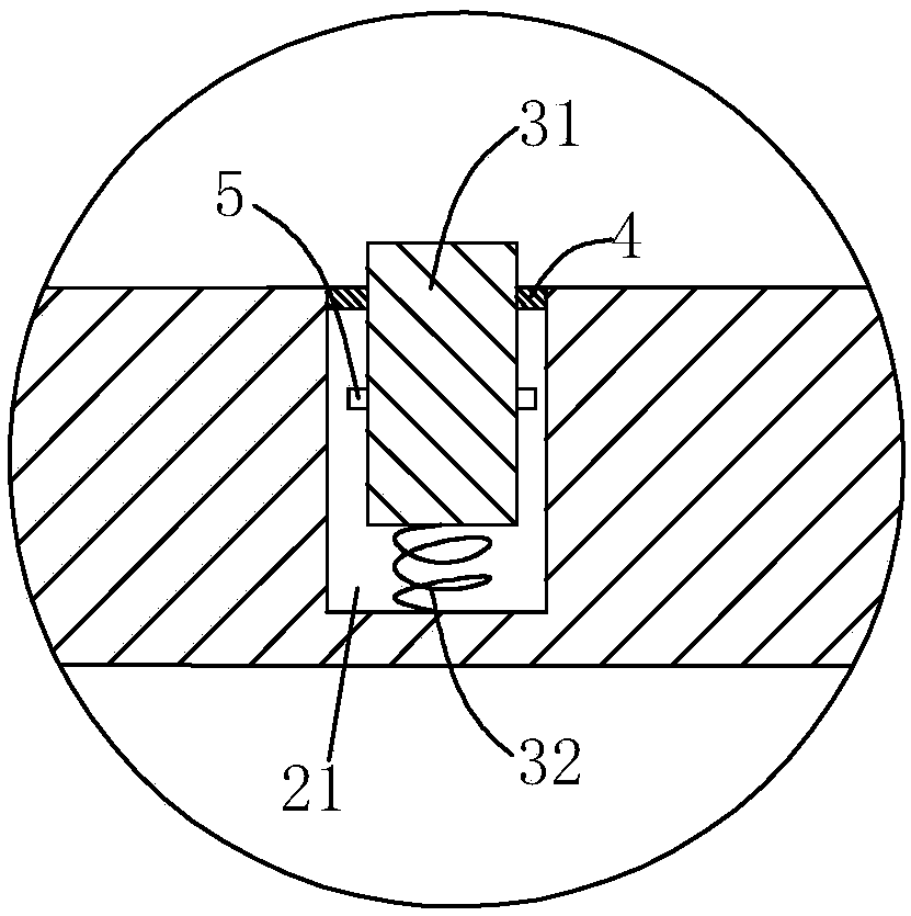
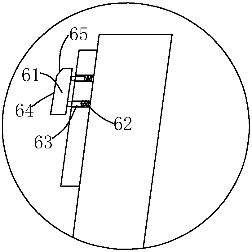
[0016] refer to Figure 1 to Figure 2 , an easy-to-use hardware handling basin of the present invention, comprising a basin body 1, said basin body 1 is flared from bottom to top, and a support member 2 is horizontally arranged on the inner wall of said basin body 1, and said support An elastic assembly 3 is provided on the member 2, and the elastic assembly 3 is used to support the bottom of the basin body 1. The support member 2 is an annular support plate surrounding the basin body 1. The elastic assembly 3 is provided with a plurality of , and the circumferential direction is evenly arranged on the support plate. When in use, the upper basin 1 can be supported on the elastic component 3 of the lower basin 1, and will not support all the weight in the hardware of the lower basin 1, especially the threaded hardware, which can effectively avoid During the process, the hardware is damaged; in addition, the upper basin body 1 and the lower basin body 1 are in contact with the ...


PUM


Abstract

The invention provides a conveniently-used hardware conveying basin. During the piling process, an upper basin body can be supported on an elastic component of a lower basin body, thus all weights cannot be supported in the hardware of the lower basin body, so that the damage of the hardware can be effectively avoided during the transportation process; besides, the bottom part of the upper basin body and the supporting piece of the lower basin body are contacted flexibly through an elastic component, thus the impact force in vertical direction during the conveying process is effectively reduced, and the damage of the hardware is further reduced; the side wall of the upper basin body can contact with the inner wall of the lower basin body through the buffer component, so that the impact force in vertical and horizontal directions during the conveying process is effectively reduced, the damage of the hardware is further reduced' the bottom part of the basin body is provided with an elastic cushion; on the one hand, the hardware contacts with the elastic cushion during the piling process, so as to reduce damage; on the other hand, the basin body can be protected from collision when the basin body is independently placed; meanwhile, a gap for lifting up conveniently is formed between the basin base and a bearing face, thus the basin is more convenient to use.

Description

technical field [0001] The invention relates to the field of hardware handling equipment, in particular to a convenient hardware handling basin. Background technique [0002] At present, the pots used to hold threaded hardware tools are generally the pots purchased on the market. During the transportation of such pots, it is necessary to pile up the pots full of screws or hardware for storage or transportation. The bottom of the previous pot will be in contact with the screws in the next pot, but when transporting this kind of pot, the bumps in the transportation will cause the bottom of the previous pot to collide with the screws in the next pot and the friction will increase, which will easily damage the screws or other screws. The threads of hardware accessories lead to a relatively high scrap rate of screws and threaded hardware; and some hardware handling basins are generally made of hard materials such as metal, which are easy to cause bumps when placed, affecting the ...

Claims


Application Information

Patent Timeline
Patent Type & Authority Applications(China)
IPC IPC(8): B65D21/032
Inventor 吴永强
Owner 吴永强
Learn More