Image defogging method based on visual optimization of sky region

A sky area and image technology, applied in image enhancement, image data processing, instruments, etc., to achieve the effect of improving sky distortion, natural defogging effect, and natural image processing effect

Inactive Publication Date: 2018-01-30
ZHEJIANG UNIV OF TECH
View PDF0 Cites 4 Cited by
  • Summary
  • Abstract
  • Description
  • Claims
  • Application Information

AI Technical Summary

Problems solved by technology

[0005] The purpose of the present invention is to propose an image defogging method for visual optimization of the sky area, which performs visual perception optimization processing on the image that h

Method used


Image

  • Image defogging method based on visual optimization of sky region
  • Image defogging method based on visual optimization of sky region
  • Image defogging method based on visual optimization of sky region

Examples


Embodiment Construction

[0043] specific implementation plan

[0044] The technical scheme of the method of the present invention will be further described below in conjunction with the accompanying drawings.

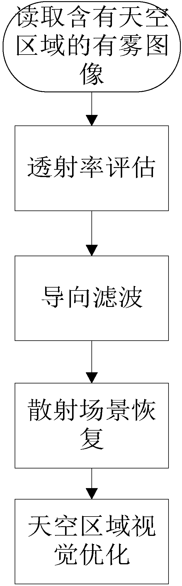
[0045] An image defogging method for visual optimization of the sky area, the steps are as follows figure 1 shown, including:

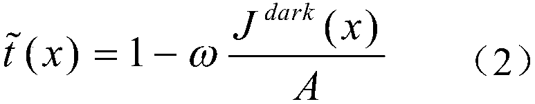
[0046] Step 1. Transmittance evaluation of hazy images containing sky regions;

[0047] First read in the foggy image I containing the sky area. The dark channel prior dehazing method works well for non-sky areas, and the dark channel prior method is used to evaluate the transmittance of foggy images including sky areas.

[0048] The specific evaluation steps are as follows:

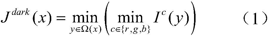
[0049] 14. According to the definition of the dark channel (that is, formula 1), calculate the dark

[0050] channel, dark channel J of I dark can be expressed as:

[0051]

[0052] Among them, x and y represent any pixel of the image, and Ω(x) represents a certain image block. I c Here...


PUM


Abstract

An image defogging method based on visual optimization of a sky region comprises a first step of evaluating the transmission rate of a fog image with the sky region; a second step of guiding and filtering transmission rate of the fog image with the sky region; a third step of recovering the scattering scene of the fog image with the sky region and a fourth step of visually optimizing the sky region of the fog image. The " halo effect " is effectively inhibited, so that the image processing effect is more natural. According to the method, visual perception optimization is carried out on a sky distortion area based on a dark channel prior defogging algorithm, and the transmission rate of the sky region is reevaluated. The sky distortion phenomenon is obviously improved, and a more natural defogging effect is presented.

Description

technical field [0001] The invention relates to a computer image processing method. Background technique [0002] With the development of security technology and the increase of network bandwidth, computer vision systems have been widely used in many fields, such as highways, urban roads, navigation, aerial photography, etc. In recent years, China and other developing countries have often been attacked by severe weather such as smog. In such extreme weather conditions, high-definition cameras will be affected by small solid particles and small droplets in the atmosphere, and the captured images often lose main information. , so that the image acquisition device cannot capture a clear image. This is because the suspended particles will scatter the light, which attenuates the light reflected by the scene, and at the same time, the scattered ambient light is mixed into the light received by the observation, which changes the contrast, color and other characteristics of the ima...

Claims


Application Information

Patent Timeline
IPC IPC(8): G06T5/00
Inventor 董天阳朱浩楠范菁杨丽锦
Owner ZHEJIANG UNIV OF TECH
Why Eureka
Try Eureka