
Two-way torque clutch based on centrifugation

A torque clutch, two-way technology, applied in the field of clutches, can solve problems such as limiting the development of mechanical business, the clutch cannot be adjusted, and the effect of the clutch is weakened.

Inactive Publication Date: 2018-02-02
DONGGUAN SONGYAN ZHIDA IND DESIGN CO LTD
View PDF0 Cites 0 Cited by
  • Summary
  • Abstract
  • Description
  • Claims
  • Application Information

AI Technical Summary

Problems solved by technology

[0002] The currently used clutch cannot adjust the torque of the clutch input shaft according to the load of the output shaft through the clutch itself during use; this greatly weakens the effect of the clutch; it brings a lot of inconvenience during use; this greatly limits The development of the mechanical industry; so it is very necessary to design a clutch that can automatically adjust the torque of the clutch input shaft according to the load of the output shaft

Method used


Image

  • Two-way torque clutch based on centrifugation
  • Two-way torque clutch based on centrifugation
  • Two-way torque clutch based on centrifugation

Examples


specific Embodiment approach

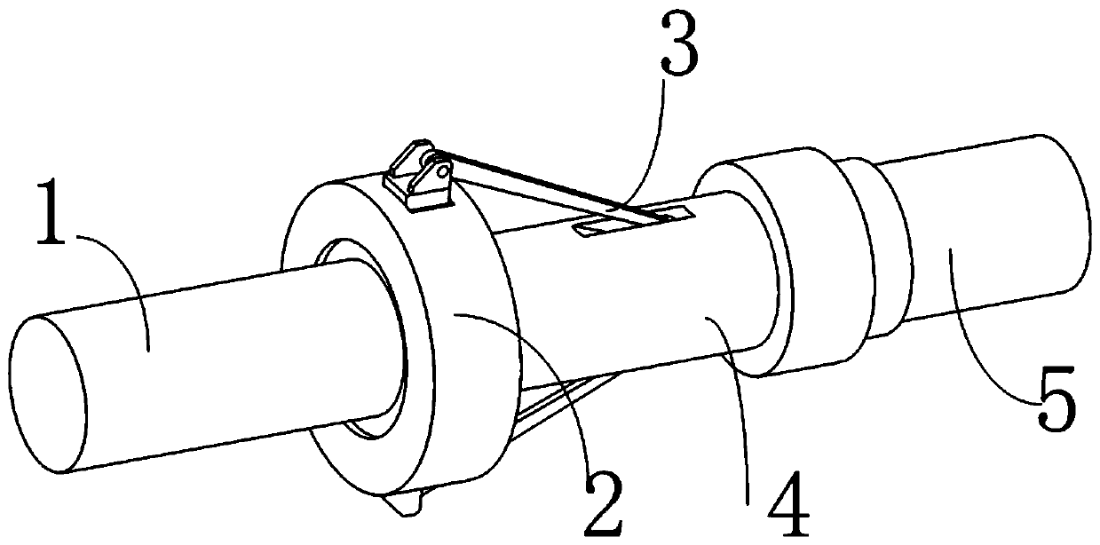
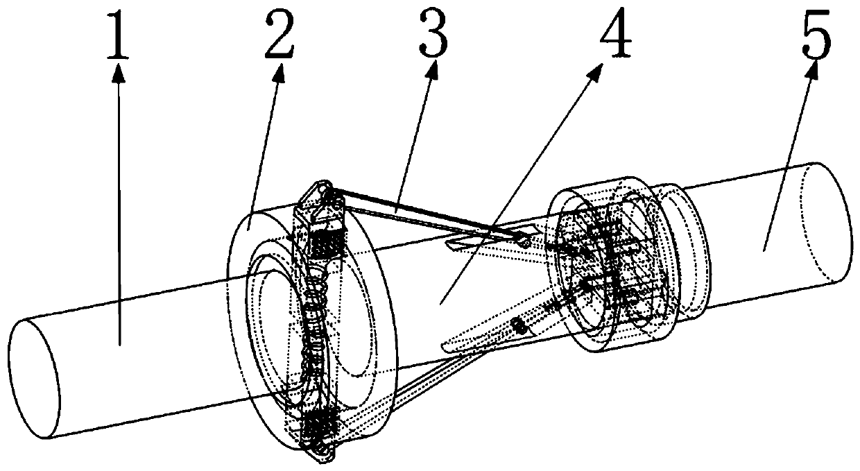
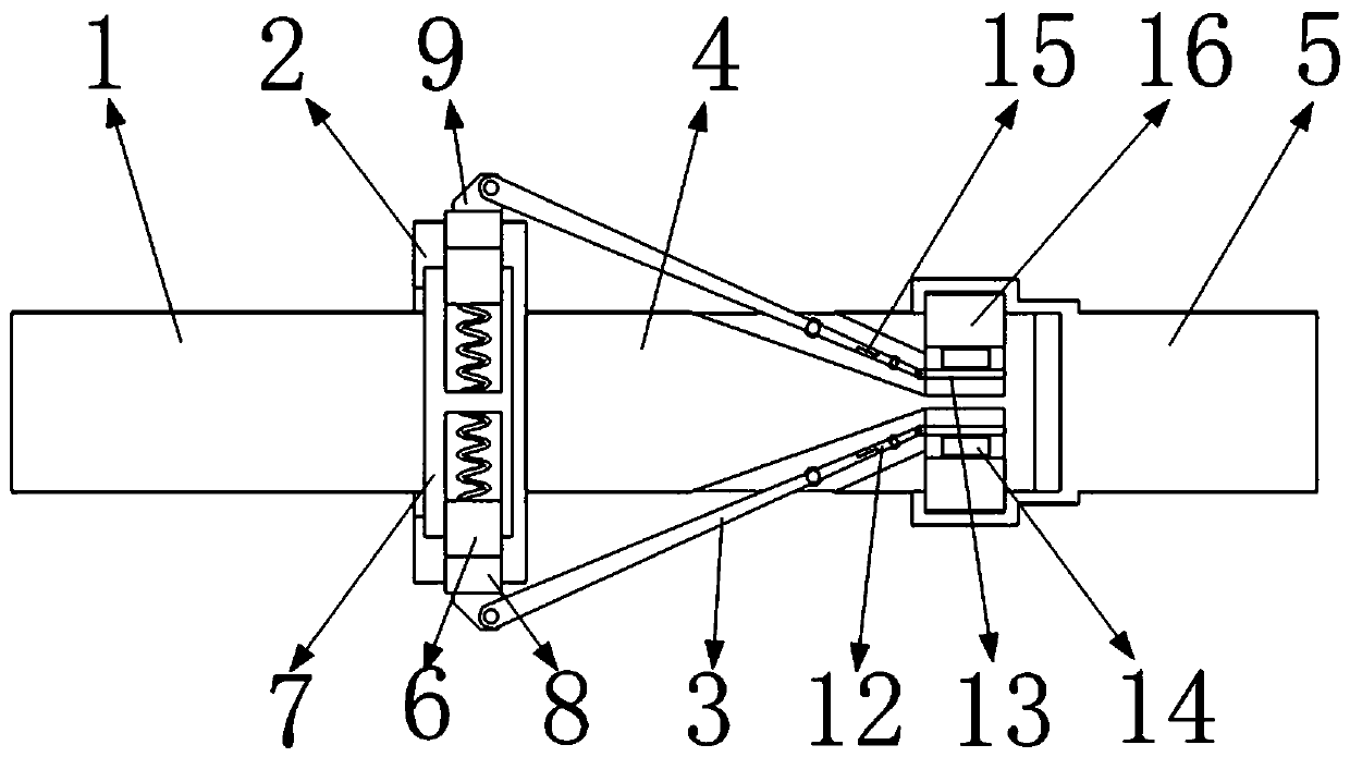
[0047] The specific embodiment: if people use the clutch designed by the present invention; when the input shaft 1 rotates; the input shaft 1 will drive the drive disc 7 to rotate; the drive disc 7 will rotate to make the centrifugal block 6 to the drive disc 7 outside Move; when the centrifugal block 6 is in contact with the arc surface on the drive slot 19 during the movement; one of the two centrifugal blocks 6 will move to the inside of the corresponding drive slot 19; the other centrifugal block 6 will Can not move to corresponding drive slot 19; The centrifugal block 6 that moves to drive slot 19 inboard in two centrifugal blocks 6 is in the moving process; This centrifugal block 6 can squeeze corresponding adjustment block 8; Make adjustment block 8 to Move away from the side of the drive plate 7; the movement of the adjustment block 8 will drive the corresponding first adjustment rod 3 to swing to the side away from the adjustment block 8 through the lugs on it; the swi...


PUM


Abstract

The invention belongs to the technical field of clutches, and in particular relates to a two-way torque clutch based on centrifugal force, which includes an input shaft, a drive ring, a first adjustment rod, a transmission shaft, an output shaft, a first drive ring, and a second drive ring. When rotating, the input shaft will drive the drive disc to rotate; the rotation of the drive disc will strengthen the extrusion force between the drive protrusion and the first drive ring; at the same time, the rotation of the centrifugal block will drive the drive ring to rotate; the drive ring will drive the drive shaft to rotate; the drive shaft The rotation drives the driving protrusion to rotate; in the present invention, there is liquid between the driving protrusion and the corresponding transmission protrusion located inside the annular space formed by the first drive ring and the transmission shaft. Therefore, the rotation of the driving protrusion will drive the corresponding transmission protrusion to rotate through the liquid; the rotation of the transmission protrusion will drive the corresponding first drive ring to rotate; the rotation of the first drive ring will drive the rotation of the second drive ring; the rotation of the second drive ring will drive the rotation of the output shaft.

Description

Technical field [0001] The invention belongs to the technical field of clutches, in particular to a centrifugal-based two-way torque clutch. Background technique [0002] The currently used clutch cannot adjust the torque of the clutch input shaft according to the load of the output shaft through the clutch itself during use; this greatly weakens the effect of the clutch; it brings a lot of inconvenience during use; this greatly limits The development of the mechanical industry; so it is very necessary to design a clutch that can automatically adjust the torque of the clutch input shaft according to the load of the output shaft. [0003] The present invention designs a centrifugal-based two-way torque clutch to solve the above problems. Contents of the invention [0004] In order to solve the above-mentioned defects in the prior art, the present invention discloses a centrifugal-based two-way torque clutch, which is realized by adopting the following technical solutions. ...

Claims


Application Information

Patent Timeline
IPC IPC(8): F16D43/16
CPCF16D43/16
Inventor 朱利强
Owner DONGGUAN SONGYAN ZHIDA IND DESIGN CO LTD
Features
  • Generate Ideas
  • Intellectual Property
  • Life Sciences
  • Materials
  • Tech Scout
  • Unparalleled Data Quality
  • Higher Quality Content
  • 60% Fewer Hallucinations
Learn More