
Vehicular power transmission system

a transmission system and transmission line technology, applied in mechanical equipment, transportation and packaging, gearing, etc., can solve problems such as increasing costs, and achieve the effects of relieving a start shock, excellent power transmission efficiency and durability, and low cos

Active Publication Date: 2007-04-05
HONDA MOTOR CO LTD
View PDF4 Cites 22 Cited by
  • Summary
  • Abstract
  • Description
  • Claims
  • Application Information

AI Technical Summary

Benefits of technology

[0007] The present invention has been made in view of such circumstances. An object of the present invention is to provide a vehicular power transmission system in which a first shift clutch and a second shift clutch to which a power of an engine is transmitted shift gear steps, the vehicular power transmission system being excellent in efficiency of power transmission and durability, and being capable of being manufactured at low cost and of relieving a start shock. Another object of the invention is to make an engine and a transmission compact. Still another object of the invention is to reduce the weight of the vehicle power transmission system by shortening an input shaft requiring strength for disposition of a first shift clutch and a second shift clutch in such a manner that the center of gravity of heavy parts such as a first shift clutch and a second shift clutch can be close to a supporting member. A further object of the invention is to improve making the operating response of the first shift clutch and the second shift clutch uniform.
[0018] The invention according to the first aspect of the present invention, a centrifugal clutch excellent in efficiency of power transmission at relatively low cost is used as a start clutch. The vehicular power transmission system in which the first shift clutch and the second shift clutch to which the power of the engine is transmitted shift gear steps is excellent in efficiency of power transmission and durability, and can be manufactured at low cost and relieve a start shock.
[0019] According to the second aspect of the present invention, the axle base between the output shaft and the input shaft can be smaller. The output shaft of the engine and the input shaft of the transmission can be arranged to be compact. The engine and the transmission can be compact.
[0020] According to the third aspect of the present invention, the center of gravity of heavy parts such as the first shift clutch and the second shift clutch can be close to the housing. The input shaft requiring strength for disposition of the first shift clutch and the second shift clutch is shortened for weight reduction.
[0021] According to the fourth aspect of the present invention, the difference in length between the oil paths 67 and 68 to the first shift clutch and the second shift clutch constructed of hydraulic clutches can be smaller, which contributes to making the operating response of the first shift clutch and the second shift clutch uniform to improve the shift feeling.
[0022] According to the fifth aspect of the present invention, the power from the centrifugal clutch is equally transmitted to the first shift clutch and the second shift clutch, which contributes to making the operating response of the first shift clutch and the second shift clutch uniform to improve the shift feeling.

Problems solved by technology

When a fluid type torque converter is used for this, efficiency of power transmission in the torque converter is not always high, so that transmission loss can cause an increase in cost.

Method used


Image

  • Vehicular power transmission system
  • Vehicular power transmission system
  • Vehicular power transmission system

Examples


Embodiment Construction

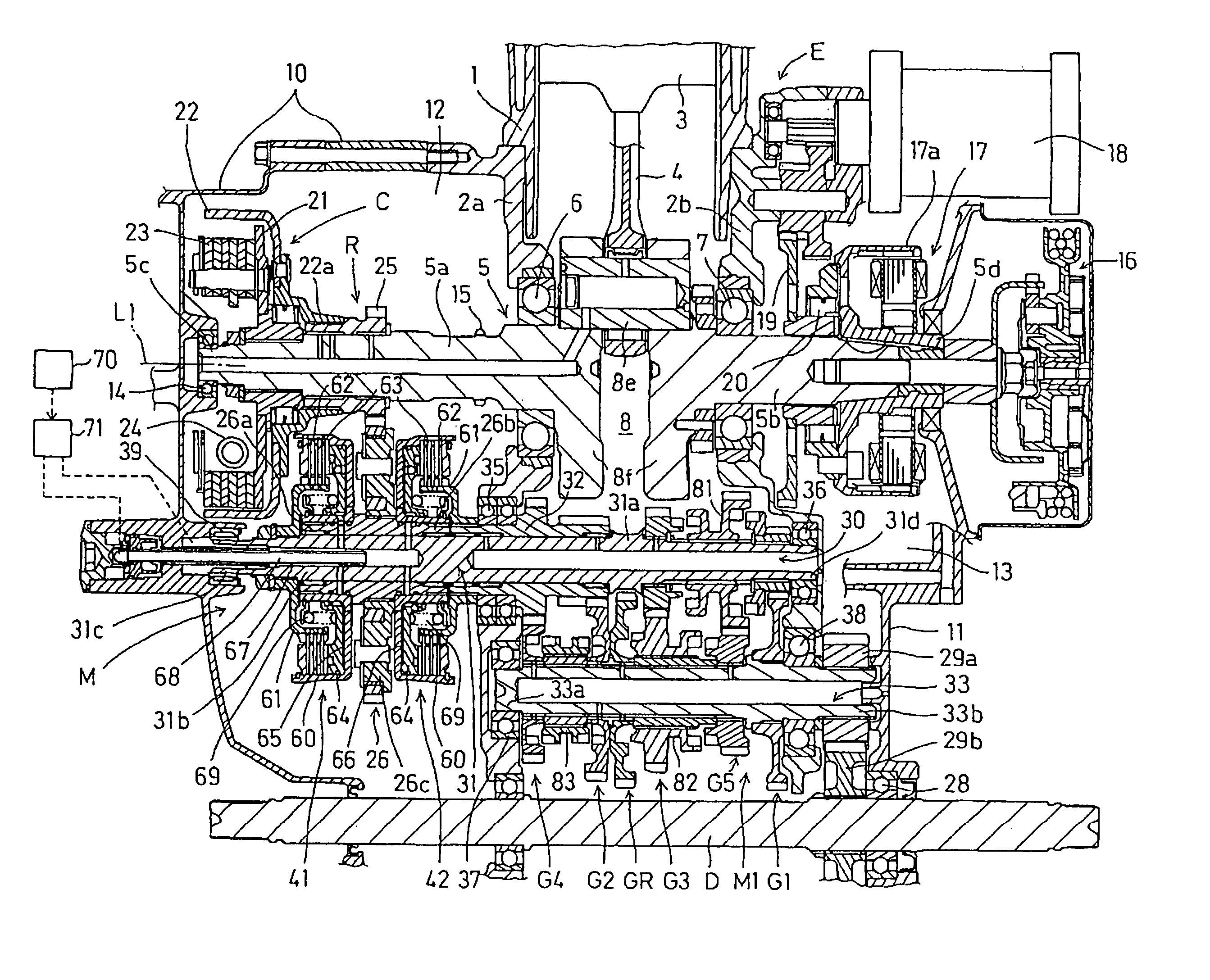
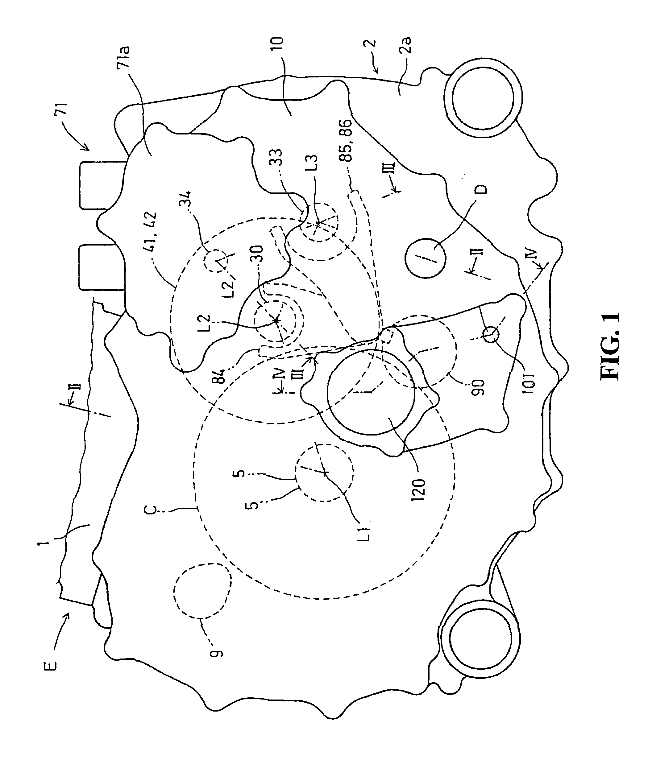
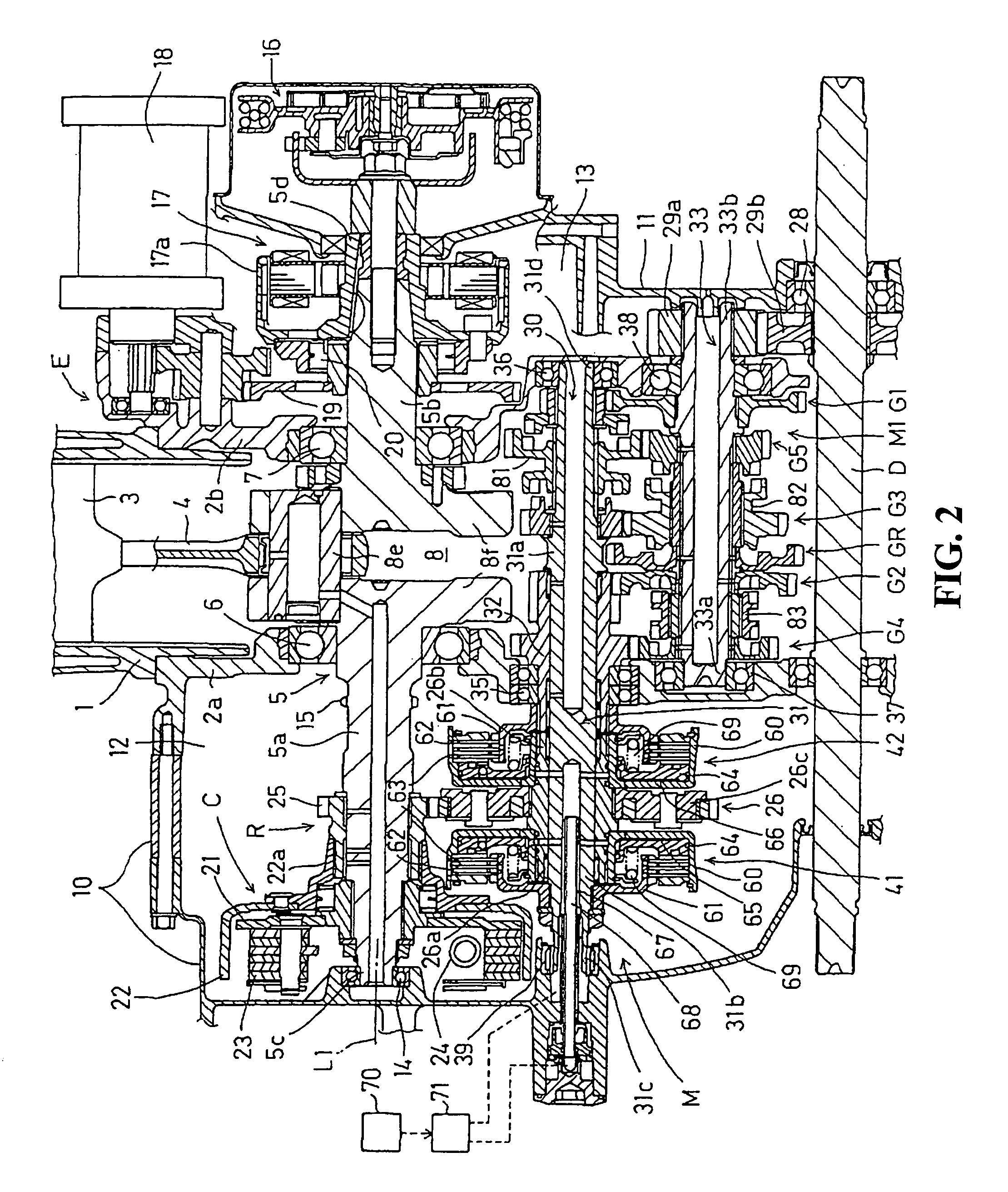
[0030] Referring to FIGS. 1 and 2, a vehicular power transmission system to which the present invention is applied constructs a power unit mounted on a saddle-ride type ATV (All Terrain Vehicle) as a vehicle together with an internal combustion engine E as an engine. The power transmission system has a constant-mesh type gear transmission M (hereinafter, called a “transmission M”) as an automatic transmission selecting gear trains G1 to G5 and GR from shift gear trains M1 to establish a running gear step, a centrifugal clutch C constructing a start clutch transmitting and interrupting a power produced by the internal combustion engine E to the transmission M, and a drive axle D to which the power shifted by the transmission M is transmitted. The power of the drive axle D is transmitted to a front wheel and a rear wheel via a front drive shaft and a rear drive shaft, and then, the wheels are rotatably driven.

[0031] The internal combustion engine 3 is a water-cooled type single-cylin...


PUM


Abstract

A transmission M of a vehicular power transmission system has a first shifting part and a second shifting part which shift a power of an internal combustion engine, a first shift clutch transmitting and interrupting the power to the first shifting part, and a second shift clutch transmitting and interrupting the power to the second shifting part. A start clutch transmitting and interrupting the power to the first shift clutch and the second shift clutch is constructed of a centrifugal clutch C having a clutch shoe. The resulting configuration provides a vehicular power transmission system which has excellent efficiency of power transmission and durability, as well as being capable of being manufactured at low cost, and being capable of relieving a start shock.

Description

CROSS-REFERENCE TO RELATED APPLICATION [0001] The present application claims priority under 35 U.S.C. §119 to Japanese Patent Application No. 2005-287983, filed Sep. 30, 2005, the entire contents of which are hereby incorporated by reference. BACKGROUND OF THE INVENTION [0002] 1. Field of the Invention [0003] The present invention relates to a vehicular power transmission system provided with a transmission, the vehicular power transmission system shifting gear steps by a first shift clutch and a second shift clutch to which a power of an engine is transmitted. [0004] 2. Description of Background Art [0005] There has been known a transmission of a vehicular power transmission system having a first shift clutch and a second shift clutch to which a power of an engine is transmitted, the shift clutches shifting gear steps (For instance, see JP-A No. 262163 / 1992, and JP-A No. 357267 / 2002). [0006] A power of an engine is gradually transmitted to a transmission at start of a vehicle to re...

Claims


Application Information

Patent Timeline
IPC IPC(8): F16H3/08B60K17/02B60K17/04B60K17/06
CPCF16H3/006F16H3/32F16H63/18Y10T74/19233F16H2063/025Y10T74/19228F16H2200/0043
Inventor MIZUNO, KINYAFUJIMOTO, YASUSHIHAMAOKA, SEIJI
Owner HONDA MOTOR CO LTD
Learn More