Solar heat collector

A solar collector and heat collection technology, which is applied in the directions of solar collectors, thermal insulation of solar collectors, components of solar collectors, etc., can solve the problem of small cross-sectional area, inconvenient installation and use, and limited water capacity. and other problems, to achieve the effect of large water holding capacity, convenient installation and use, and good heat insulation effect.

Inactive Publication Date: 2018-02-02
成立
View PDF3 Cites 3 Cited by
  • Summary
  • Abstract
  • Description
  • Claims
  • Application Information

AI Technical Summary

Problems solved by technology

In the existing heat collector structure, the cross-sectional area of ​​the inner and outer tanks is small, the water ho

Method used


Image

  • Solar heat collector
  • Solar heat collector
  • Solar heat collector

Examples


Embodiment 1

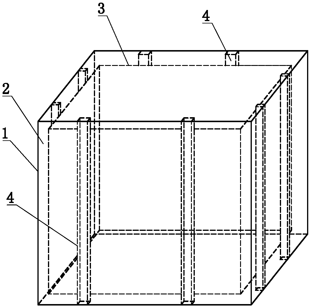
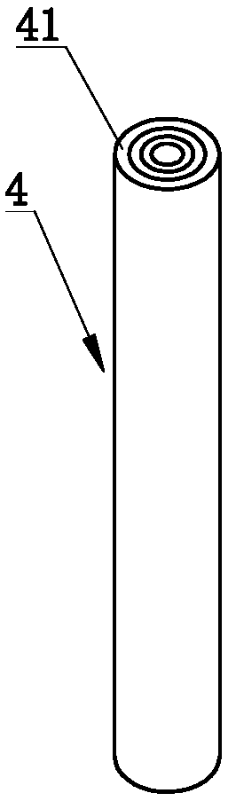
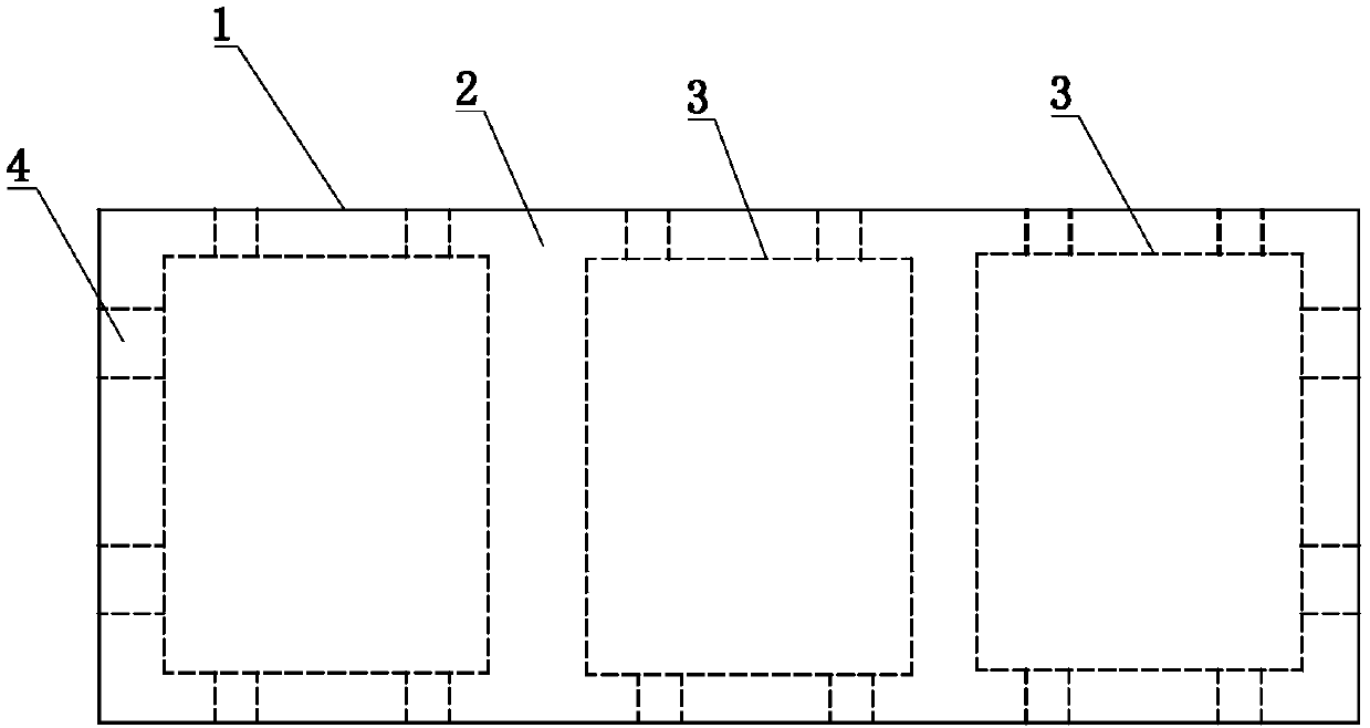
[0023] refer to figure 1 and figure 2 , The solar heat collector of this embodiment includes a front transparent shell 1, and the front of the shell 1 is its sunny side. The housing 1 is surrounded by a vacuum chamber 2, and the housing 1 is provided with a control valve (not shown) for vacuuming. The housing chamber 2 is provided with a heat collection container 3, and the outer surface of the heat collection container 3 A heat conduction spacer is provided between the inner surface of the corresponding shell 1, and the heat conduction spacer is a long heat conduction spacer 4, and the long heat conduction spacer 4 extends from one end of the surface of the heat collection container 3 to the opposite end. The shape of the heat collecting container 3 can adopt various shapes such as square, cuboid, cylinder, semicylindrical. The shell 1 can be made of glass as a whole to form an overall transparent glass shell. In order to enhance the strength of the shell 1, the back of th...

Embodiment 2

[0031] refer to Figure 4 , the structure of the solar heat collector of the present embodiment is basically the same as that of Embodiment 1, the difference is that the heat conduction spacer is a heat conduction spacer block 5 arranged at intervals from one end to the opposite end of the surface of the heat collection container 3 , forming a broken bridge structure, the heat conduction spacer 5 can also be formed by layer-by-layer hollow casings, and can also be in the shape of a square. The contact area further improves the heat insulation effect.


PUM


Abstract

The invention discloses a solar heat collector. The solar heat collector comprises a housing, front surface of which is transparent, wherein the housing defines a vacuumized accommodating cavity; a heat collecting container is arranged in the accommodating cavity; and a thermal conduction isolating part is arranged between the outer surface of the heat collecting container and the inner surface ofthe corresponding housing. The solar heat collector disclosed by the invention is convenient to mount and use, and is great in water containing amount.

Description

technical field [0001] The invention relates to the technical field of solar water heaters, in particular to a solar heat collector. Background technique [0002] Solar water heaters have been widely used in people's lives. In existing solar water heaters, the heat collector includes multiple vacuum tubes, each vacuum tube includes an outer tank and an inner tank, and the vacuum is drawn between the outer tank and the inner tank. The thermal layer, the sunlight passes through the outer tank and shines on the heat absorbing layer of the inner tank, absorbing the heat of the solar light energy. [0003] Since the outer tank and the inner tank are vacuum-insulated, there is no heat conduction and heat convection, only radiation heat transfer remains, and the heat transfer is greatly reduced. Most of the heat can only be transferred to the water in the inner tank, making the inner tank The water inside is heated. In the existing heat collector structure, the cross-sectional ar...

Claims


Application Information

Patent Timeline
IPC IPC(8): F24S10/40F24S70/10F24S70/20F24S80/60
CPCY02E10/44
Inventor 成立
Owner 成立
Why Eureka
Try Eureka