
Shell manufacturing method

A manufacturing method and shell technology, which are applied in the direction of manufacturing tools, forging/pressing/hammering machinery, casings/cabinets/drawer parts, etc., can solve the problem of large deviation of the edge size on both sides of the boss, reducing the shell Body yield and other issues

Active Publication Date: 2018-02-06
GUANGDONG OPPO MOBILE TELECOMM CORP LTD
View PDF4 Cites 3 Cited by
  • Summary
  • Abstract
  • Description
  • Claims
  • Application Information

AI Technical Summary

Problems solved by technology

This will lead to a large deviation in the size of the sides of the processed boss, or a large eccentricity after the camera is assembled. Therefore, the existing shell manufacturing method will reduce the yield of the shell.

Method used


Image

  • Shell manufacturing method
  • Shell manufacturing method
  • Shell manufacturing method

Examples


Embodiment Construction

[0031] The following will clearly and completely describe the technical solutions in the embodiments of the present invention with reference to the accompanying drawings in the embodiments of the present invention. Obviously, the described embodiments are only some, not all, embodiments of the present invention. Based on the embodiments of the present invention, all other embodiments obtained by persons of ordinary skill in the art without making creative efforts belong to the protection scope of the present invention.

[0032] In the description of the embodiments of the present invention, it should be understood that the orientation or positional relationship indicated by the term "thickness" is based on the orientation or positional relationship shown in the drawings, and is only for the convenience of describing the present invention and simplifying the description, rather than implying Or an indication that the device or element referred to must have a particular orientati...


PUM


Abstract

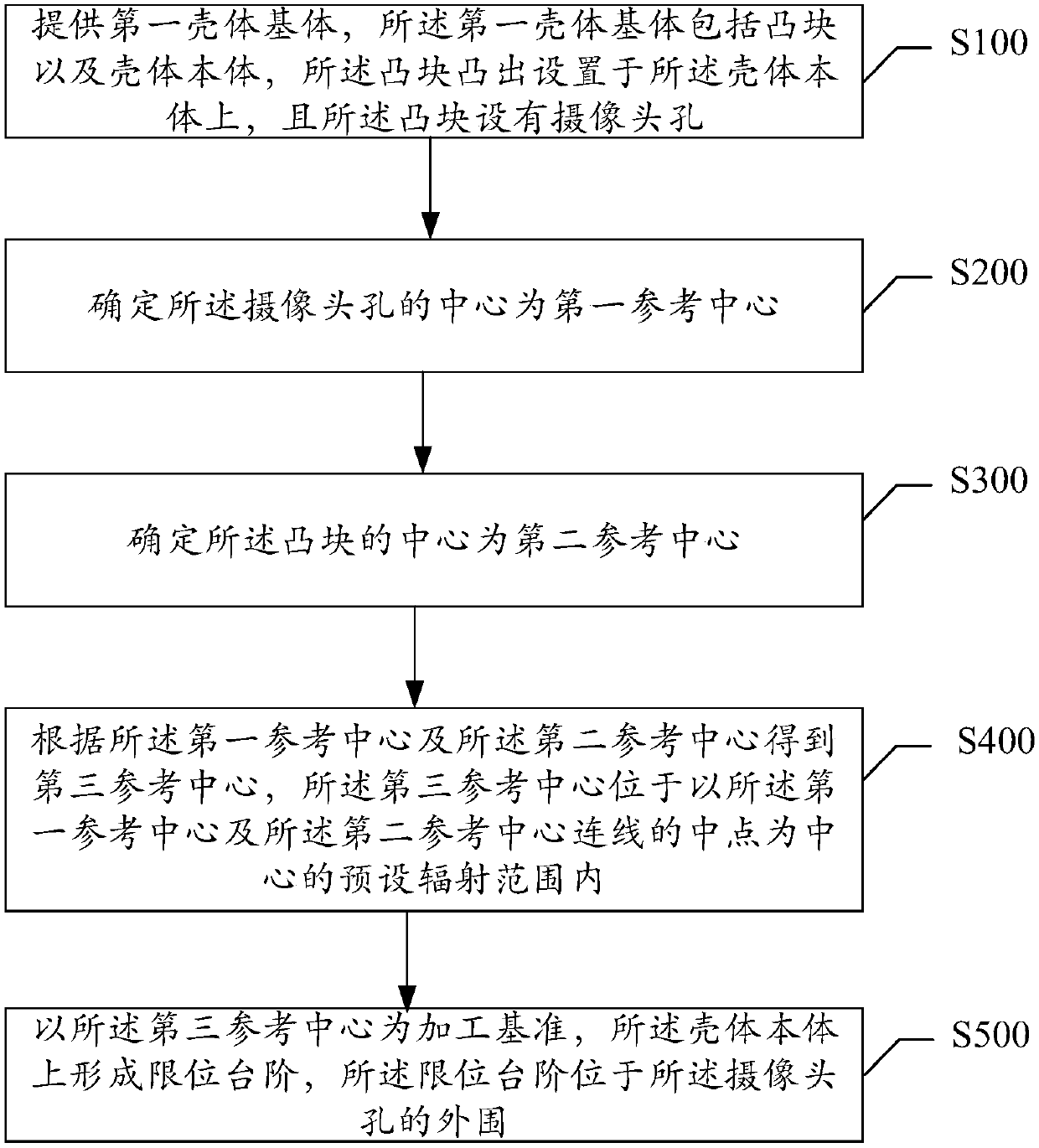
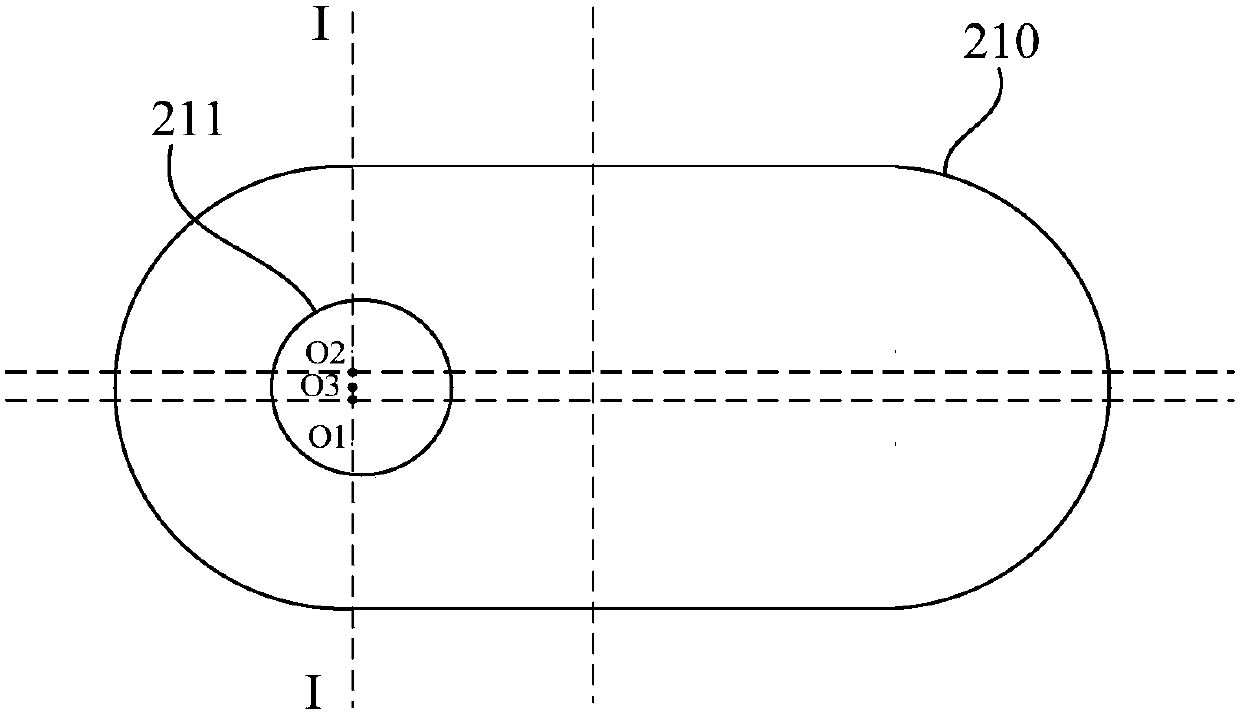
The invention provides a shell manufacturing method. The shell manufacturing method comprises the following steps of providing a first shell matrix, wherein the first shell matrix comprises a convex block and a shell body, and the convex block provided with a camera hole is arranged on the shell body in a protruding mode; determining the center of the camera hole as a first reference center; determining the center of the convex block as a second reference center; according to the first reference center and the second reference center, obtaining a third reference center, wherein the third reference center is located in a preset radiation range taking the midpoint of the connecting line of the first reference center and the second reference center as the center thereof; taking the third reference center as a processing reference, and forming a limiting step on the shell body, wherein the limiting step is located on the periphery of the camera hole. According to the shell manufacturing method, the size deviation of machined edges on the two sides of the convex block is prevented from being large. Meanwhile, the eccentricity of the camera on the shell is prevented from being large.

Description

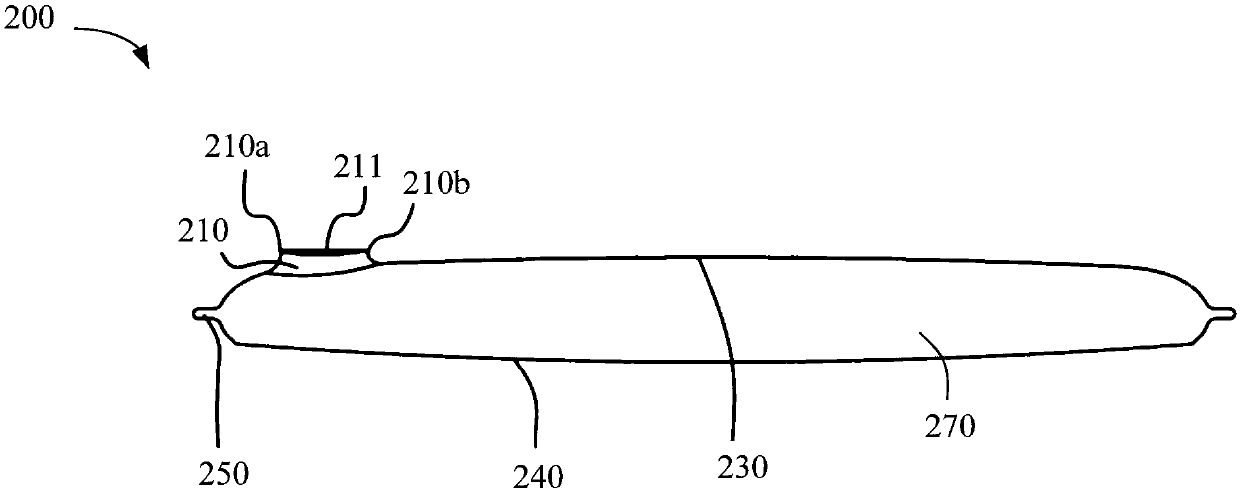
technical field [0001] The invention relates to the field of electronic equipment, in particular to a method for manufacturing a casing. Background technique [0002] Mobile devices such as mobile phones usually include parts such as housings. When the shell is manufactured, a plate with relatively uniform thickness (for example, aluminum material) is usually provided, and then the plate is subjected to forging and pressing processes to form the shell. The casing is usually provided with a boss protruding from the casing body, and a camera hole is arranged on the boss, and the camera hole is used to expose the camera part, so that the camera can take pictures when taking pictures. The step of processing the boss on the housing body and the step of processing the camera hole are usually completed at different clamping positions, and the processing standards are unified. This will lead to a large deviation in the size of the sides of the processed boss, or a large eccentrici...

Claims


Application Information

Patent Timeline
IPC IPC(8): H05K5/02B21J5/02B21J13/02
CPCB21J5/02B21J13/02H05K5/0217
Inventor 唐义梅
Owner GUANGDONG OPPO MOBILE TELECOMM CORP LTD
Learn More