Valve arrangement for hermetic compressors

A valve device and compressor technology, applied in valve devices, components of pumping devices for elastic fluids, control valves, etc., can solve problems such as reducing reliability and increasing impact force, reducing stress, viscosity, etc. The effect of reducing the attached area and reducing the adhesion force

Inactive Publication Date: 2014-02-26
WHIRPOOL SA
View PDF9 Cites 0 Cited by
  • Summary
  • Abstract
  • Description
  • Claims
  • Application Information

AI Technical Summary

Problems solved by technology

If asymmetry occurs when the valve vane is closed, a part of the vane may reach the valve seat before the rest of the vane sealing part, sharply increasing the impact force and reducing the reliability of the valve

Method used


Image

  • Valve arrangement for hermetic compressors
  • Valve arrangement for hermetic compressors
  • Valve arrangement for hermetic compressors

Examples


Embodiment Construction

[0037] The present invention will describe a hermetic compressor for use in a refrigeration system, such as a domestic or commercial refrigeration system of the type previously described.

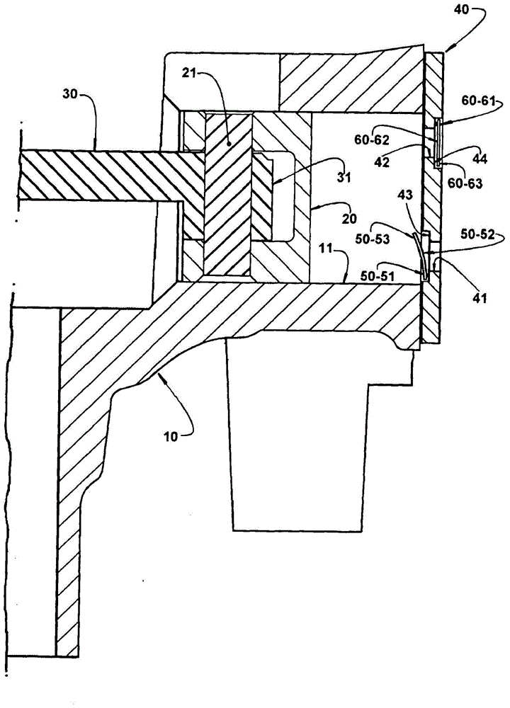
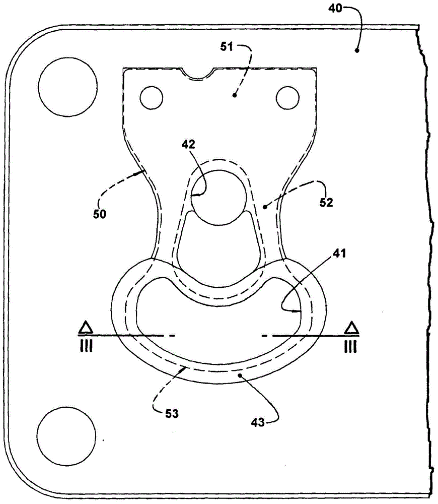
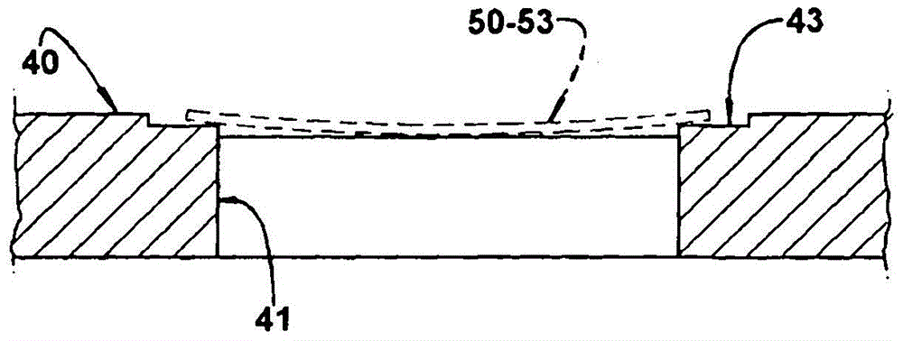
[0038] The hermetic compressor comprises: a cylinder crankcase 10 defining a compression cylinder 11; a valve plate 40 which closes one end of the compression cylinder 11 and is provided with a suction hole 41 and a discharge hole 42 and their respective seating areas 43, 44, each of said Both the suction hole 41 and the discharge hole 42 are closed by respective valve suction vanes 50 and valve discharge vanes 60 .

[0039] Each suction vane 50 and each discharge vane 60 has: a mounting end 51, 61 for attachment to the valve plate 40; a curved central portion 52, 62; The associated sealing ends 53, 63 and are displaced by elastic deformation between a valve-closed position blocking the passage of gas through the respective suction orifice 41 and discharge orifice 42, and a valve-opening po...


PUM


Abstract

The arrangement can be applied to a compressor which comprises a compression cylinder (11) closed by a valve plate (40) provided with seat regions (43, 44) and with respective suction orifice (41) and discharge orifice (42) which are closed by a sealing end portion (53, 63) of a respective valve vane (50, 60), to be peripherally seated against its seat region (43, 44). The valve plate (40) carries a support means (70), defined in the central region of the contour of at least one of the suction orifice (41) and discharge orifice (42) and incorporated to the valve plate (40) by at least one radial arm (80). The support means (70) has a stop surface (71), against which is seated a central region of the sealing end portion (53, 63) of the respective vane (50, 60), said stop surface (71) defining a projection in relation to the radial arm (80).

Description

technical field [0001] The present invention relates to a structural arrangement of seats for valve blades of hermetic compressors for refrigeration systems, such as domestic refrigeration systems, such as refrigerators, freezers, drinking fountains and the like. [0002] The invention applies in particular to hermetic compressors comprising a cylinder crankcase forming a compression cylinder closed at one end by a valve plate provided with suction and discharge holes accommodated in the inner contour of the compression cylinder's axial projection . At least one suction hole and one discharge hole are each closed by a respective flexible reed valve having a mounting end attached to the valve plate, a curved middle and a sealing end which is in contact with the valve plate The holes in are operatively associated. Background technique [0003] The energy efficiency of small hermetic refrigeration compressors is mainly due to the good performance of the suction and discharge ...

Claims


Application Information

Patent Timeline
Patent Type & Authority Applications(China)
IPC IPC(8): F04B39/10
CPCF04B39/1066F04B39/1073F16K15/10F04B39/10F04B53/1087
Inventor F·法戈蒂
Owner WHIRPOOL SA
Why Eureka
Try Eureka