Spine posterior device

A posterior approach and spine technology, applied in spinal implants, medical science, prostheses, etc., can solve the problems that the posterior column of the spine cannot be reconstructed, so as to reduce postoperative risks, promote bone healing, and promote bone ingrowth Effect

Active Publication Date: 2018-02-09
北京理贝尔生物工程研究所有限公司
View PDF14 Cites 0 Cited by
  • Summary
  • Abstract
  • Description
  • Claims
  • Application Information

AI Technical Summary

Problems solved by technology

[0005] The main purpose of the present invention is to provide a method to solve the problem in

Method used


Image

  • Spine posterior device
  • Spine posterior device
  • Spine posterior device

Examples


Example Embodiment

[0024] It should be noted that the embodiments in the present application and the features of the embodiments may be combined with each other in the case of no conflict. The present invention will be described in detail below with reference to the accompanying drawings and in conjunction with the embodiments.

[0025] It should be noted that the following detailed description is exemplary and intended to provide further explanation of the application. Unless otherwise defined, all technical and scientific terms used herein have the same meaning as commonly understood by one of ordinary skill in the art to which this application belongs.

[0026] For ease of description, spatially relative terms, such as "on", "over", "on the surface", "above", etc., may be used herein to describe what is shown in the figures. The spatial positional relationship of one device or feature shown to other devices or features. It should be understood that spatially relative terms are intended to e...


PUM


Abstract

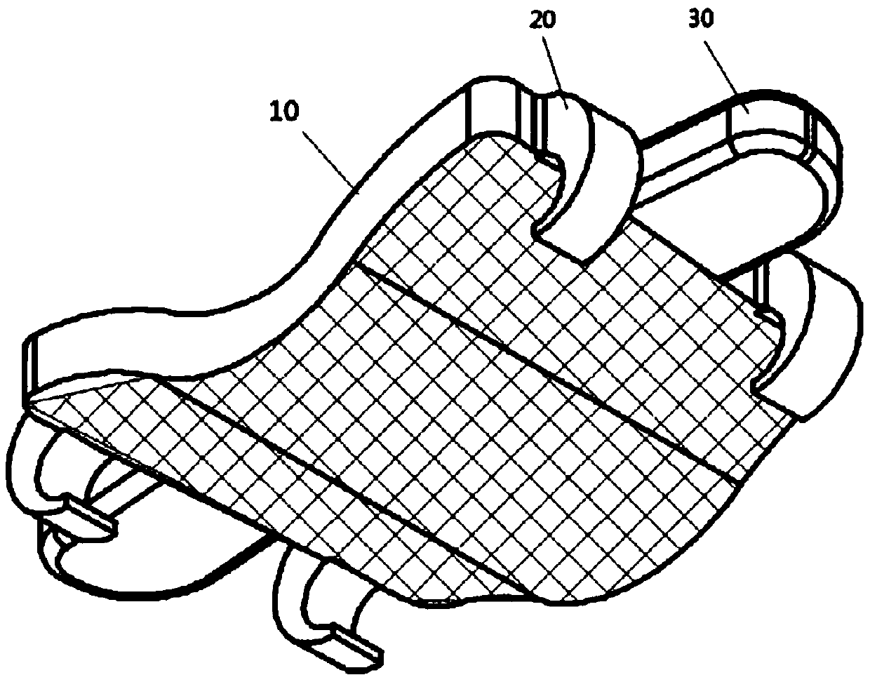
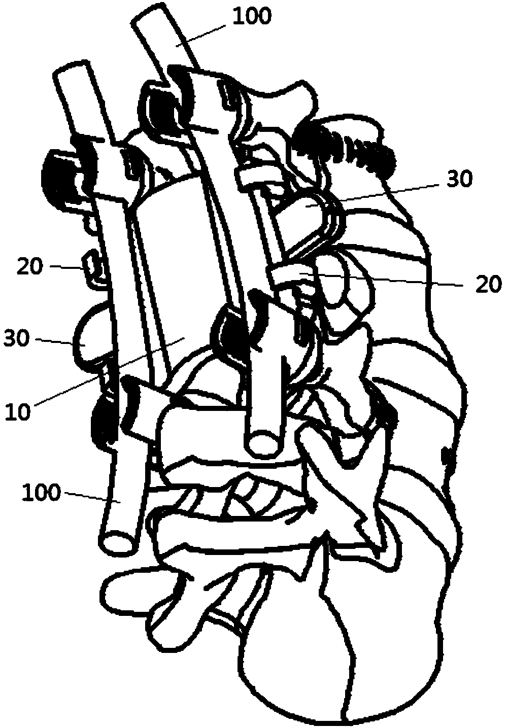
The invention provides a spine posterior device. The device comprises a device body and a connection part; the device body is arranged on the side, away from the vertebral body of the human body, of the spine, and is used for promoting bone ingrowth; the connection part is arranged on the device body and used for being connected with a posterior nail bar to fix the device body. According to the spine posterior device, the connection part is connected with the posterior nail bar, accordingly, the device body is positioned at the osteotomy portion, the position of the device body is equal to theposterior column part, the device body can promote bone ingrowth, bone healing of the posterior column part is promoted, finally the posterior column part of the spine is rebuilt, long-term stabilityis achieved, and the post-operation risk is lowered.

Description

technical field [0001] The invention relates to the field of medical instruments, in particular to a posterior spinal device. Background technique [0002] The human spine will be damaged due to illness or external force, such as vertebral body tumors, severe comminuted fractures, and infectious diseases such as tuberculosis, which may lead to spinal cord and nerve damage or collapse of vertebral segments and angular deformity of the spine. Vertebrectomy is often required in patients with obvious neurological dysfunction or angular deformity. [0003] The stability of the human spine is determined by the structure of the spine. According to the three-column theory, it is distinguished from the anatomical shape of the spine. The anterior longitudinal ligament of the spine and the anterior 1 / 3 of the vertebrae are the anterior column of the spine, and the posterior 2 / 3 of the vertebrae is the anterior column of the spine. The posterior longitudinal ligament forms the middle c...

Claims


Application Information

Patent Timeline
IPC IPC(8): A61F2/44
CPCA61F2/44A61F2002/3093
Inventor 李健
Owner 北京理贝尔生物工程研究所有限公司
Why Eureka
Try Eureka