A multi-functional intelligent vehicle-mounted unit and its control method
An on-board unit and control method technology, applied in ticketing equipment, instruments, etc., can solve the problems of single OBU function and lack of interconnection
- Summary
- Abstract
- Description
- Claims
- Application Information
AI Technical Summary
Problems solved by technology
Method used
Image

Examples
Embodiment 1
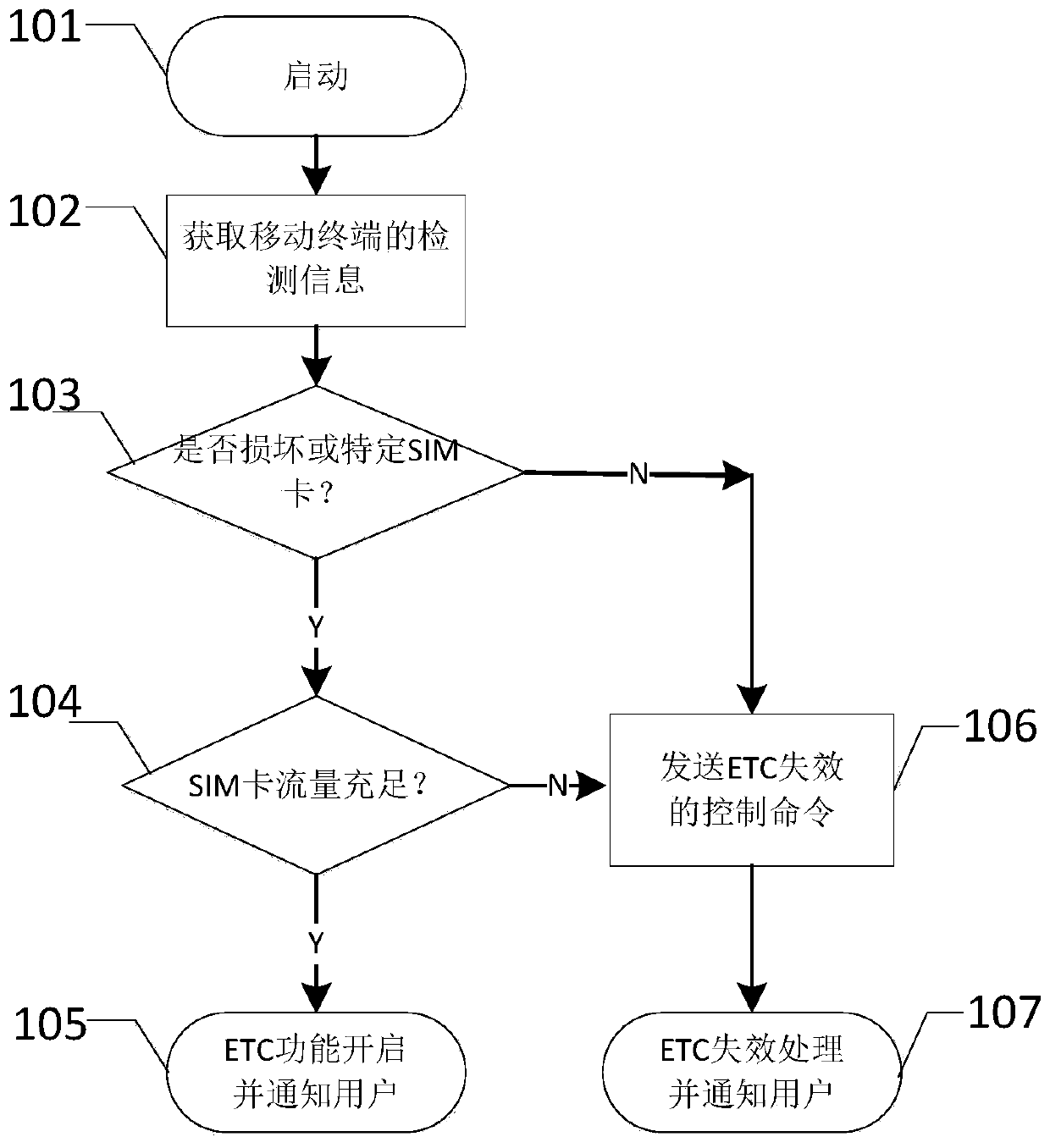
[0039] Embodiment 1, a vehicle-mounted unit control method, the workflow is as follows figure 2 shown.
[0040] Mainly include steps:
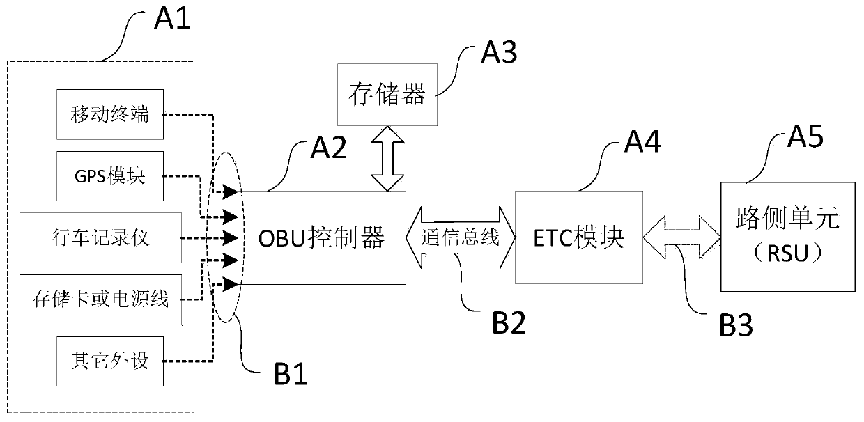
[0041] 101. Power on and start the additional function module A1, the OBU controller A2, and the ETC module A4. The additional function module A1 is a mobile terminal.
[0042] Power-on start can be regarded as two states, namely power-on state and working state. The power-on state refers to the initialization state of the electronic device before it enters the working state. For example, the ETC function of the ETC module is set to be enabled by default (this setting may not be set according to the product’s own function definition), and its own hardware information is detected and read. The process takes a short time and takes place only once at power-up. The working state refers to the stage after the electronic device completes the power-on state, and the electronic device will continue to realize its own functions and maintain this s...
Embodiment 2
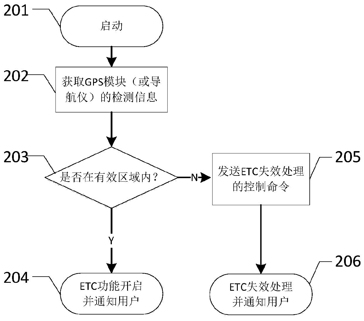
[0062] Embodiment 2, a method for controlling a vehicle-mounted unit, the workflow is as follows image 3 shown.
[0063] Mainly include steps:
[0064] 201. Power on and start the additional function module A1, the OBU controller A2, and the ETC module A4. The additional function module A1 is a GPS module or a navigator.
[0065] In the present embodiment, the function class detection information B1 (such as location information) of GPS module or navigator is continuously produced in its working process, therefore, the following steps (steps 202 to 206) are considered to be the execution process of the system working state .
[0066] 202. The OBU controller A2 obtains the detection information B1 of the GPS module or the navigator through active or passive communication, and the detection information B1 includes the location information of the GPS module or the navigator.
[0067] For the active communication mode and the passive communication mode, reference may be made ...
Embodiment 3
[0076] Embodiment 3, a method for controlling a vehicle-mounted unit, the workflow is as follows Figure 4 shown.
[0077] Mainly include steps:
[0078] 301. Power on and start the additional function module A1, the OBU controller A2, and the ETC module A4. The additional function module A1 is a driving recorder.
[0079] In this embodiment, the functional detection information B1 (such as image information) of the driving recorder is continuously generated during its working process. Therefore, the following steps (steps 302 to 307) are considered as the execution process of the system working state.
[0080]302. The OBU controller A2 acquires detection information B1 of the driving recorder through active or passive communication, and the detection information B1 includes captured image information.
[0081] For the active communication mode and the passive communication mode, reference may be made to step 102 in Embodiment 1, and details are not repeated here.
[0082]...
PUM
 Abstract
Description
Claims
Application Information
 - R&D Engineer
- R&D Manager
- IP Professional
- Industry Leading Data Capabilities
- Powerful AI technology
- Patent DNA Extraction
Browse by: Latest US Patents, China's latest patents, Technical Efficacy Thesaurus, Application Domain, Technology Topic.
© 2024 PatSnap. All rights reserved.Legal|Privacy policy|Modern Slavery Act Transparency Statement|Sitemap