Aerial cable shock absorber with insulation performance

A high-altitude cable and shock absorber technology, which is applied in the field of shock absorption equipment, can solve problems such as cable high-altitude shock absorption and cable breakage, and achieve the effects of preventing cable breakage, stopping cable shaking, and high shock absorption efficiency

Active Publication Date: 2018-02-09
JIANGSU ELECTRIC POWER CO
View PDF9 Cites 2 Cited by
  • Summary
  • Abstract
  • Description
  • Claims
  • Application Information

AI Technical Summary

Problems solved by technology

[0004] The technical problem to be solved by the present invention is that the cable is prone to violent vibration and breakage at high altitude, and the purpose is to provide a high-altitude cable shock absorber with insulation function to solve the problem of high-altitude cable shock absorption

Method used


Image

  • Aerial cable shock absorber with insulation performance

Examples


Embodiment 1

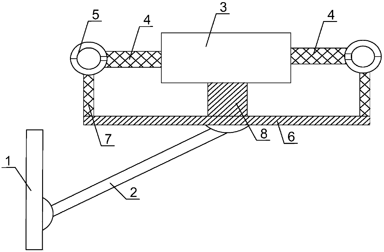
[0022] Such as figure 1 As shown, the high-altitude cable shock absorber with insulation function of the present invention includes a base 1, the base 1 is connected and fixed with the pole connecting the cable, the base 1 is connected with the shock absorber through the connecting rod 2, and the shock absorber The device includes a fixed plate 3, a first spring 4 connected to the fixed plate 3, and a plastic ring 5 connected to the first spring 4. One side of the fixed plate 3 is connected with a support plate 6 parallel to the fixed plate 3 to support Plate 6 is connected with connecting rod 2, one end of connecting rod 2 is hinged with base 1, the other end of connecting rod 2 is hinged with support plate 6, both sides of fixed plate 3 are connected with first spring 4, each first spring 4 Plastic rings 5 ​​are arranged on both, and the first spring 4 located on the same side of the fixing plate 3 is connected with the cable through the plastic ring 5, and the plastic ring ...

Embodiment 2

[0025] Based on Embodiment 1, a second spring 7 is connected between the plastic ring 5 and the support plate 6 , and the second spring 7 is perpendicular to the support plate 6 . In the present invention, the synergistic effect of the first spring and the second spring can simultaneously play a shock-absorbing effect on the cable in the vertical direction and the horizontal direction.

Embodiment 3

[0027] Based on the above embodiment, the plastic ring 5 is composed of two semi-circular rings hinged together. The hinged end of the plastic ring 5 is close to the first spring 4. One end of the two semi-circular rings is hinged and the other end can rotate around the hinged end. One end of the two semicircles rotating around the hinged end is connected by a magnet. The plastic ring is composed of two half rings, which is easy to open the ring for the cable to enter the ring, easy to use, and the magnets are connected stably.


PUM


Abstract

The invention discloses an aerial cable shock absorber with insulation performance. The aerial cable shock absorber comprises a base, wherein the base is fixedly connected with an electric pole for connecting cables; the base is connected with a shock absorber through a connecting rod; the shock absorber comprises a fixed plate, first springs connected onto the fixed plate and plastic rings connected onto the first springs; one side of the fixed plate is connected with a supporting plate parallel to the fixed plate; the supporting plate is connected with the connecting rod; one end of the connecting rod is articulated with the base, and the other end of the connecting rod is articulated with the supporting plate; two sides of the fixed plate are connected with the first springs respectively; each of the first springs is provided with the corresponding plastic ring respectively; the first springs positioned on the same side of the fixed plate are connected with the cables through the corresponding plastic rings; and the plastic rings are connected onto the cables in a sleeving manner. The two cables are connected together through the fixed plate and the first springs, the two cablesplay a role of interaction under the effect of the first springs, and simultaneously, the effect of shock absorption is achieved.

Description

technical field [0001] The invention relates to a shock absorber, in particular to a high-altitude cable shock absorber with insulation function. Background technique [0002] The cable is usually a rope-like cable twisted by several or groups of wires [at least two in each group]. Each group of wires is insulated from each other and is often twisted around a center. Insulating covering. It is mostly erected in the air or installed underground or underwater for telecommunications or power transmission; the difference between it and ordinary wires is that the cable size is larger and the structure is more complicated. [0003] The cables in high school will shake violently in the vertical or horizontal direction under the wind blowing or animal collision. During the shaking process, the connection end of the cable and the pole will generate a large torsion force, resulting in the cable and the electric pole. The connecting segment end of the rod vibrates and breaks. Conte...

Claims


Application Information

Patent Timeline
Patent Type & Authority Applications(China)
IPC IPC(8): H02G7/14
CPCH02G7/14
Inventor 杨浩
Owner JIANGSU ELECTRIC POWER CO
Why Eureka
Try Eureka