Stepped mounting structure of inclined surface suspended ceiling

A technology for installing structures and slopes, applied in the direction of ceilings, building components, building structures, etc., can solve the problems of danger, unstable and firm connection structure, etc., and achieve the effects of convenient construction, good link effect and simple structure.

Pending Publication Date: 2021-08-31
ZHEJIANG YASHA DECORATION
View PDF1 Cites 0 Cited by
  • Summary
  • Abstract
  • Description
  • Claims
  • Application Information

AI Technical Summary

Problems solved by technology

In this installation structure, there is an unstable and firm connection structure between gypsum boards, which may cause danger after a long time.

Method used


Image

  • Stepped mounting structure of inclined surface suspended ceiling
  • Stepped mounting structure of inclined surface suspended ceiling
  • Stepped mounting structure of inclined surface suspended ceiling

Examples


Embodiment 1

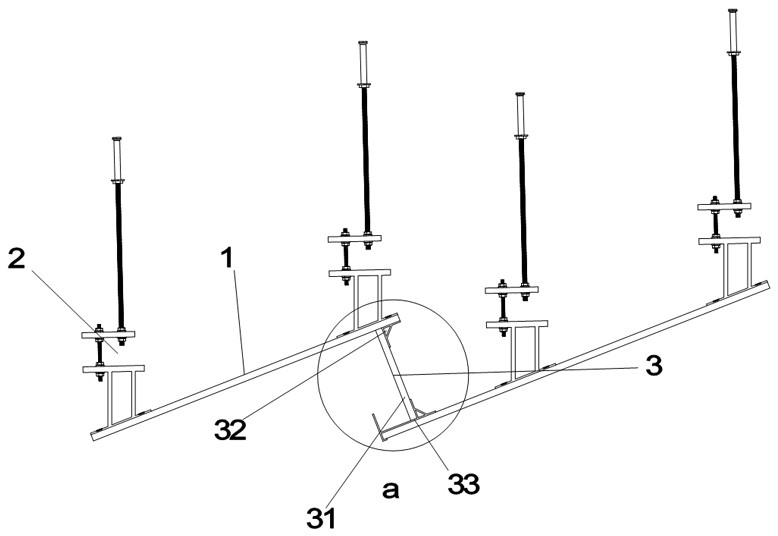
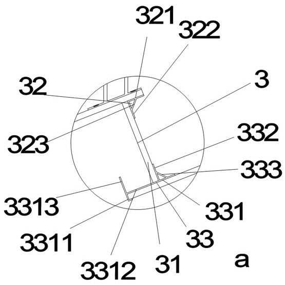
[0029] A drop-down installation structure for a sloped ceiling, comprising several suspended ceiling panels 1 inclined and arranged in parallel, a suspension assembly 2 for suspending the suspended ceiling panels 1, and an inter-panel connection assembly for connecting adjacent suspended ceiling panels 1 3. The ceiling panel 1 has a high-position end and a low-position end, and it is characterized in that: the inter-panel connection assembly 3 includes a vertical frame plate 31, an upper connector 32 and a lower connector 33, and the upper connector 32 has A panel bonding portion 311 for connecting the high end of a suspended ceiling panel 1 and a frame plate bonding portion 312 for connecting the upper end of the vertical frame plate 31, the lower connector 33 has a The panel fixing portion 331 connecting the lower ends of the adjacent ceiling panels 1 and a frame panel connecting portion 332 for connecting the lower end of the vertical frame panel 31 .

[0030] In the presen...

Embodiment 2

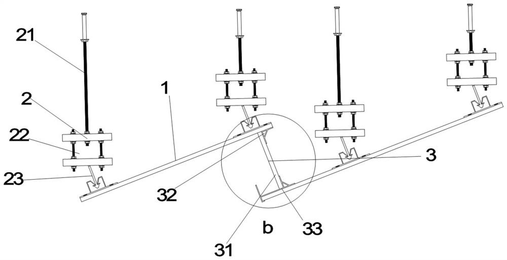
[0041] A drop-down installation structure for a sloped ceiling, comprising several suspended ceiling panels 1 inclined and arranged in parallel, a suspension assembly 2 for suspending the suspended ceiling panels 1, and an inter-panel connection assembly for connecting adjacent suspended ceiling panels 1 3. The ceiling panel 1 has a high-position end and a low-position end, and it is characterized in that: the inter-panel connection assembly 3 includes a vertical frame plate 31, an upper connector 32 and a lower connector 33, and the upper connector 32 has A panel bonding portion 311 for connecting the high end of a suspended ceiling panel 1 and a frame plate bonding portion 312 for connecting the upper end of the vertical frame plate 31, the lower connector 33 has a The panel fixing portion 331 connecting the lower ends of the adjacent ceiling panels 1 and a frame panel connecting portion 332 for connecting the lower end of the vertical frame panel 31 .

[0042] In the presen...


PUM


Abstract

The invention provides a stepped mounting structure of an inclined surface suspended ceiling. The stepped mounting structure comprises a plurality of suspended ceiling panels, suspension assemblies used for suspending the suspended ceiling panels and inter-plate connecting assemblies used for connecting the adjacent suspended ceiling panels. Each inter-plate connecting assembly comprises a vertical frame plate, an upper connecting piece and a lower connecting piece. Each upper connecting piece comprises a panel attaching part fixed with a high-position suspended ceiling panel and a frame plate attaching part fixedly connected with the vertical frame plate, the lower connecting piece comprises a frame plate connecting part and a panel fixing part, the frame plate connecting part is connected with the vertical frame plate, the lower surface of the panel fixing part is attached to a low-position suspended ceiling panel, and the lower surface of the panel fixing part is attached to the lower-position suspended ceiling panel. The stepped mounting structure of the inclined surface suspended ceiling is stable in structure and high in risk resistance.

Description

technical field [0001] The invention belongs to the technical field of building decoration, and in particular relates to a drop-down installation structure for a slanted ceiling. Background technique [0002] In today's society, people's requirements for house decoration are getting higher and higher. For the beauty of the house, people usually install a suspended ceiling under the ceiling and make appropriate decorations on the top surface of the room. The suspended ceiling structure can not only beautify the indoor environment and create a colorful It also has the functions of heat preservation, heat insulation, sound insulation and sound absorption, and it can also provide concealment for electrical, ventilation and air conditioning, communication and fire protection, alarm pipeline equipment and other projects. Home decoration ceilings have become a common link in home decoration. Suspended ceilings can be divided into flat ceilings and inclined ceilings. In the existing...

Claims


Application Information

Patent Timeline
Patent Type & Authority Applications(China)
IPC IPC(8): E04B9/00E04B9/18E04B9/20E04B9/22
CPCE04B9/00E04B9/18E04B9/20E04B9/22
Inventor 丁泽成王文广周东珊钱依玲余广
Owner ZHEJIANG YASHA DECORATION
Why Eureka
Try Eureka