Efficient light composite material frame

A composite material, lightweight technology, applied in the direction of material gluing, rod connection, connecting components, etc., can solve the problems of limited space utilization, weight reduction, disadvantage, etc.

Active Publication Date: 2020-10-27
AEROSPACE INST OF ADVANCED MATERIALS & PROCESSING TECH
View PDF10 Cites 4 Cited by
  • Summary
  • Abstract
  • Description
  • Claims
  • Application Information

AI Technical Summary

Problems solved by technology

Because the thickness increases in the direction perpendicular to the fram...

Method used


Image

  • Efficient light composite material frame
  • Efficient light composite material frame
  • Efficient light composite material frame

Examples


Embodiment Construction

[0025] In order to make the above objects, features and advantages of the present invention more comprehensible, the present invention will be further described in detail below through specific embodiments and accompanying drawings.

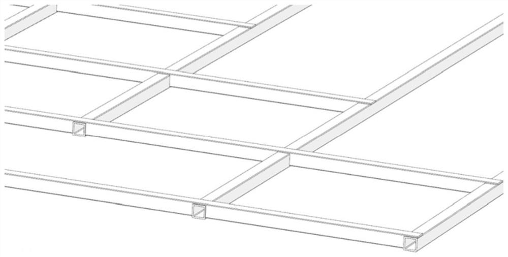
[0026] figure 1 It is a structural diagram of a high-efficiency lightweight composite material frame according to an embodiment of the present invention. The composite material frame includes several composite material pipe beams, and mortise and mortise grooves similar to mortise and tenon structures are arranged at the connection parts between the pipe beams, and the composite material pipe beams are spliced ​​together through the mortise and hole grooves to form a composite material frame.

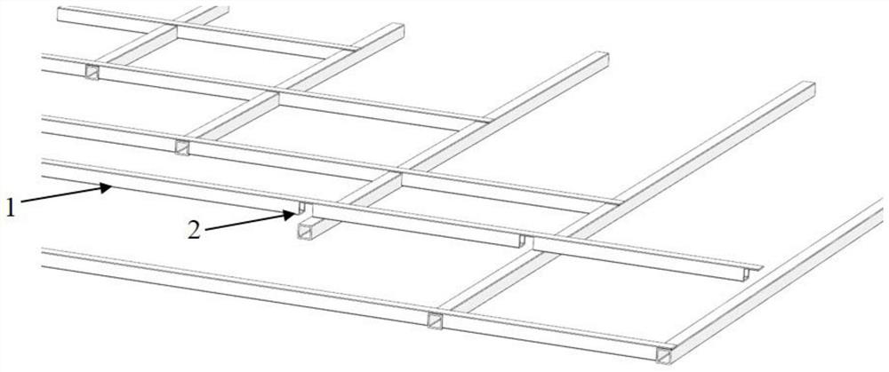
[0027] When the composite frame is fabricated, such as figure 2 As shown, the pipe beam 1 of composite material structure is processed first, and then the mortise and tenon groove 2 similar to the mortise and tenon structure is processed according to the...


PUM


Abstract

The invention relates to an efficient light composite material frame. The composite material frame comprises at least two composite material tubular beams, wherein the composite material tubular beamsare provided with mortise grooves, and fixedly connected through the mortise grooves. The mortise grooves can be formed in the composite material tubular beams in the same direction, and no mortise groove is formed in the composite material tubular beams in the other direction in order to improve the integral rigidity. Double openings can be formed in the joint of two connected composite materialtubular beams, the depth of the opening in one composite material tubular beam is the wall thickness of the tubular beam, the depth of the opening in the other composite material tubular beam is obtained by subtracting the single-side wall thickness from the integral thickness of the composite material tubular beam, and a reinforcing block is arranged in the opening at the joint. The composite material tubular beams are of a continuous structure, and the rigidity and strength of the frame are not reduced due to a connection surface formed by sections, so that the efficiency of the material can be improved, and the defects in the connection way of a conventional continuous fiber enhanced composite material frame constructed by beam frames are overcome.

Description

technical field [0001] The invention mainly relates to the application field of continuous fiber-reinforced composite material grids and frame structures, and in particular relates to a high-efficiency and lightweight composite material frame. Background technique [0002] Compared with metal materials, continuous fiber reinforced composite materials have the advantages of high specific strength and high specific modulus, and have irreplaceable application advantages in lightweight structures. Composite material frame structure, in order to ensure lighter weight and greater rigidity, generally use tubular and T-shaped profiles, and then form a frame through connections. [0003] Metal materials are easy to process, and welding can be used for frame structures, with simple process and excellent structural strength. Compared with metal materials, composite materials can only be processed by co-curing, bonding, and mechanical connection. These processes often require special m...

Claims


Application Information

Patent Timeline
IPC IPC(8): F16B7/00F16B7/18F16B11/00F16S5/00
CPCF16B7/00F16B7/18F16B11/006F16S5/00
Inventor 张辰威欧秋仁毕向军张铁夫赵宏杰吕通缪伟民
Owner AEROSPACE INST OF ADVANCED MATERIALS & PROCESSING TECH
Why Eureka
Try Eureka