Supercharge Your Innovation With Domain-Expert AI Agents!

Intake system and its control method

A control method and technology for an air intake system, which are applied to the charging system, fuel air intake, fuel air filter, etc., can solve the problem of incomplete use of the filter element and other problems, and achieve the effect of cost saving

Active Publication Date: 2020-08-11
SAIC GENERAL MOTORS +1
View PDF6 Cites 0 Cited by
  • Summary
  • Abstract
  • Description
  • Claims
  • Application Information

AI Technical Summary

Problems solved by technology

[0003] Under normal circumstances, the replacement of the filter element is determined according to the driving mileage or time in the user maintenance manual, but the actual situation is that the use degree of the filter element is not completely consistent in different cities, different working conditions and different driving habits.

Method used


Image

  • Intake system and its control method
  • Intake system and its control method

Examples


Embodiment Construction

[0046] The specific implementation manner of the present invention will be further described below in conjunction with the accompanying drawings.

[0047] It is easy to understand that, according to the technical solution of the present invention, those skilled in the art can replace various structural modes and implementation modes without changing the essence and spirit of the present invention. Therefore, the following specific embodiments and drawings are only exemplary descriptions of the technical solution of the present invention, and should not be regarded as the entirety of the present invention or as a limitation or restriction on the technical solution of the invention.

[0048] The directional terms such as up, down, left, right, front, back, front, back, top, and bottom that are mentioned or may be mentioned in this specification are defined relative to the structures shown in the drawings, and they are It is a relative concept, so it may change accordingly accord...


PUM


Abstract

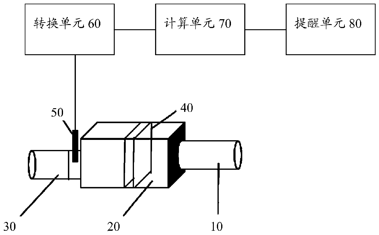
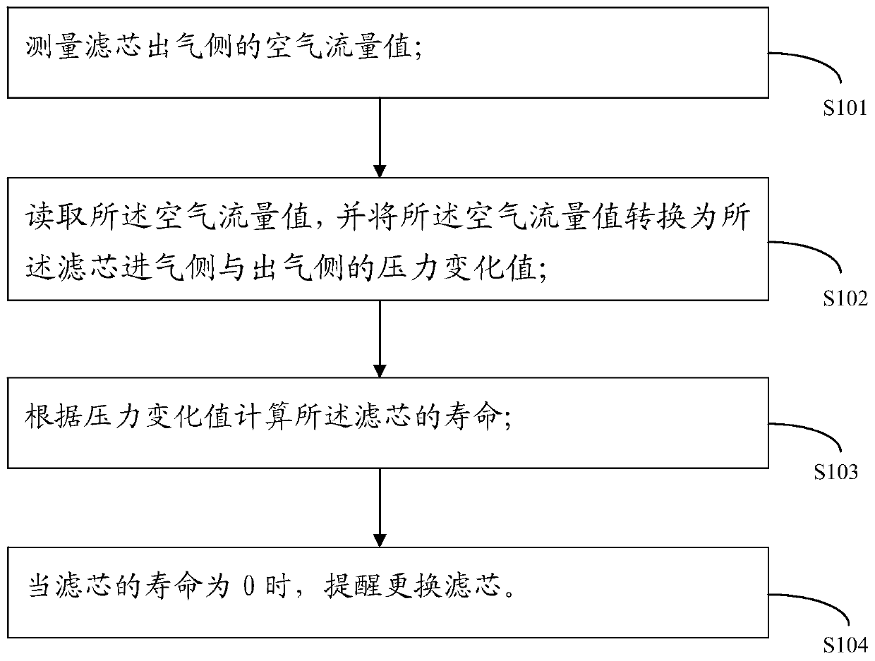
The invention discloses a control method of an air inlet system. The control method of the air inlet system comprises the following steps of S101, measuring an air flow value of an air outlet side ofa filter element; S102, reading the air flow value, and converting the air flow value into a pressure change value between an air inlet side and the air outlet side of the filter element; S103, calculating the life of the filter element according to the pressure change value; and S104, when the life of the filter element is 0, reminding a user of replacing the filter element. The invention furtherdiscloses the air inlet system. The air flow value is converted into the pressure change value, so that the life of the filter element is calculated, and the user is automatically reminded of replacing the filter element. Therefore, the filter element can achieve a lasting and most effective function, the cost can be saved, and air feeding into an engine can still keep at a clean state.

Description

technical field [0001] The invention relates to the technical field of air filters, in particular to an intake system and a control method thereof. Background technique [0002] One of the main functions of the air filter is to filter the air, provide clean and cool air for the engine, use it for combustion and work, and minimize the wear and tear on the engine cylinder by dust particles. The main working principle is that dirty air passes through the filter element, dust, etc. Contaminants remain on one side of the filter element and cannot pass through, and the filtered clean air enters the engine. [0003] Under normal circumstances, the replacement of the filter element is determined according to the mileage or time in the user maintenance manual, but the actual situation is that the use degree of the filter element is not completely consistent in different cities, different working conditions and different driving habits. [0004] Therefore, it is necessary to design a...

Claims


Application Information

Patent Timeline
Patent Type & Authority Patents(China)
IPC IPC(8): F02M35/09F02M35/024F02M35/10
CPCF02M35/024F02M35/09F02M35/10
Inventor 刘凯刘军许明锐
Owner SAIC GENERAL MOTORS
Features
  • R&D
  • Intellectual Property
  • Life Sciences
  • Materials
  • Tech Scout
  • Unparalleled Data Quality
  • Higher Quality Content
  • 60% Fewer Hallucinations
Learn More