A clutch master cylinder structure with power assist

A master cylinder and booster block technology, applied in the field of auto parts, can solve the problems of increased clutch separation force, too large clutch pedal force, inability to increase booster springs, etc., and achieve the effect of reducing pedal force

Inactive Publication Date: 2019-04-16
ANHUI JIANGHUAI AUTOMOBILE GRP CORP LTD
View PDF13 Cites 0 Cited by
  • Summary
  • Abstract
  • Description
  • Claims
  • Application Information

AI Technical Summary

Problems solved by technology

[0002] As the torque of the automobile engine increases, the model of the matching clutch becomes larger and larger, and the separation force of the clutch also increases, resulting in a relatively large clutch pedal force. In the prior art, the pedal force is reduced by adding a booster spring to the clutch pedal. There needs to be enough space for the pedals, if there is not enough space, the booster spring cannot be added

Method used


Image

  • A clutch master cylinder structure with power assist
  • A clutch master cylinder structure with power assist
  • A clutch master cylinder structure with power assist

Examples


Embodiment Construction

[0019] The embodiments described below with reference to the accompanying drawings are exemplary and are only used to explain the present invention, but not to be construed as a limitation of the present invention.

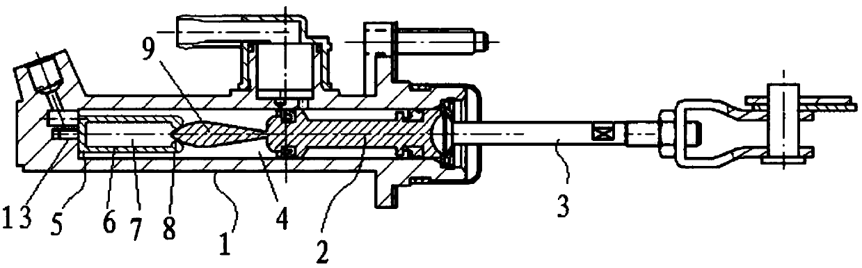
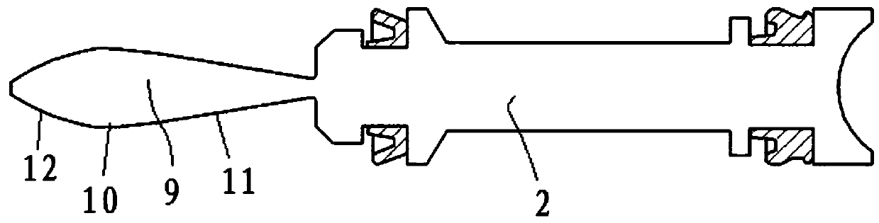
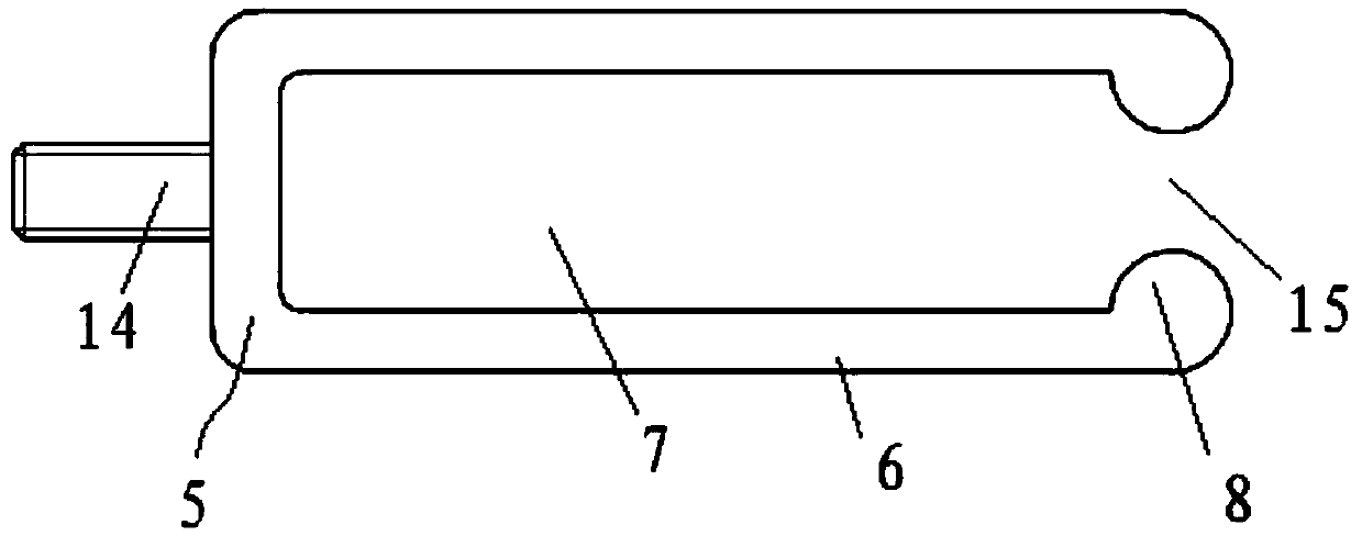
[0020] like Figure 1 to Figure 3 As shown, the embodiment of the present invention provides a power-assisted clutch master cylinder structure, including: a master cylinder block assembly 1, which has a working chamber 4; a master cylinder piston assembly 2, which is accommodated in the working chamber 4 ; Push rod assembly 3, one end extends into the working chamber 4 and is connected to the master cylinder piston assembly 2; Spring fork 5, fixed in the working chamber 4, the spring fork 5 has an accommodating space 7 , an opening 15 is formed at the opposite end of the accommodating space 7 and the master cylinder piston assembly 2; the master cylinder piston assembly 2 is provided with a booster block 9, and the free end of the booster block 9 faces the spring ...


PUM


Abstract

The invention discloses a clutch main cylinder structure with assisted power. The clutch main cylinder structure comprises a main cylinder body assembly, a main cylinder piston assembly, a push rod assembly and a spring fork. The main cylinder body assembly is provided with a work cavity, the main cylinder piston assembly is contained in the work cavity, and one end of the push rod assembly extends into the work cavity and is connected with the main cylinder piston assembly. The spring fork is fixed into the work cavity and provided with a containing space, and an opening is formed in the end,opposite to the main cylinder piston assembly, of the containing space. A power-assisted block is arranged on the main cylinder piston assembly, the free end of the power-assisted block extends towards the spring fork, and a power-assisted inflection point is formed on the outer circumferential face of the power-assisted block in a protruding mode. According to the clutch main cylinder structurewith the assisted power, the occupied space is small, meanwhile, the magnitude and the characteristic curve of the assisted power can be rapidly adjusted by adjusting the shape of the power-assisted block, and the characteristic curve of separating force of a clutch can be perfectly matched.

Description

technical field [0001] The invention relates to the technical field of auto parts, in particular to a clutch master cylinder structure with power assist. Background technique [0002] As the torque of the automobile engine increases, the model of the matching clutch becomes larger and larger, and the separation force of the clutch also becomes larger, resulting in a large clutch pedal force. In the prior art, the pedal force is reduced by adding a booster spring on the clutch pedal, which There needs to be enough space in the pedals, if there is not enough space, the booster spring cannot be added. SUMMARY OF THE INVENTION [0003] The purpose of the present invention is to provide a clutch master cylinder structure with power assist to solve the deficiencies in the prior art, which can effectively reduce the pedal force without occupying space. [0004] The invention provides a clutch master cylinder structure with power assist, comprising: [0005] The main cylinder bl...

Claims


Application Information

Patent Timeline
Patent Type & Authority Patents(China)
IPC IPC(8): F16D25/08
CPCF16D25/08F16D2025/081
Inventor 马成汪江王鑫董恒施超孟祥伟
Owner ANHUI JIANGHUAI AUTOMOBILE GRP CORP LTD
Why Eureka
Try Eureka