
Self-aligning clutch release bearing

A separation bearing, self-alignment technology, applied in the direction of clutches, mechanically driven clutches, bearings, etc., can solve the problems of loose parts, noise bearing ring wear, etc.

Inactive Publication Date: 2020-06-05
TEXSPIN BEARINGS LTD
View PDF2 Cites 0 Cited by
  • Summary
  • Abstract
  • Description
  • Claims
  • Application Information

AI Technical Summary

Problems solved by technology

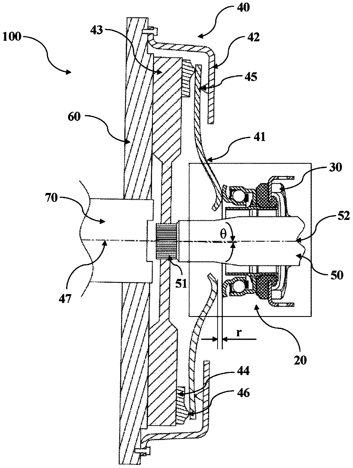
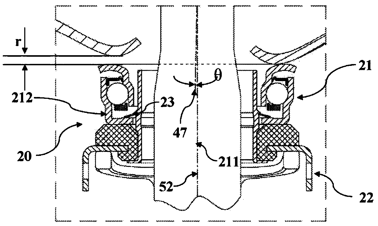
[0019] 2. The deflection r of the spring 41
[0020] 3. Misalignment θ of the axis of rotation of the clutch and the driven shaft,
However, the device included loose spherical rings, which caused noise, vibration, and wear of the bearing rings
[0026] Therefore, the available prior art teaches about clutch release bearings, which have the disadvantages of loose parts, extra material, and extra machining

Method used


Image

  • Self-aligning clutch release bearing
  • Self-aligning clutch release bearing
  • Self-aligning clutch release bearing

Examples


no. 2 example

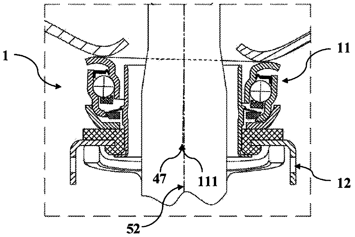
[0134] The second embodiment of the present invention provides the self-aligning clutch release bearing 1A of the present invention as an improvement over the conventional bearing 11A.

[0135] Such as Figure 5 As shown in, the improvement includes a cover 16. The bearing 11A is press-fitted in the cover 16. The cover 16 includes an outer spherical surface 161 and an inner spherical surface 162. The spherical surface 161 has a radius R1 that is the same as the radius of the spherical cup 13. In addition, the spherical surface 162 has the same radius R2 as the radius of the spherical ring 14. The cover 16 is preloaded between the spherical cup 13 and the spherical ring 14 by a spring 15. The center point of the spherical surface is at the same position on point 10. In this embodiment, the cover 16 and the bearing 11A can be tilted around the point 10 and compensate for the yaw r and misalignment θ. Therefore, the present invention allows the conventional clutch bearing to be...


PUM


Abstract

A self-aligning clutch release bearing is disclosed, comprising: a rotating ring (114) and a static ring (112). Static ring (112) is located within a spherical cup (13), which incorporates an inner spherical surface (131), and static ring (112) engages with spherical cup (13) through the spherical surface (131). Spherical surface (131) has a radius whose center coincides with a center point defined by intersection of the rotational axis (111) of the bearing and a plane defined by face of the rotating ring (114) that engages with fingers of the clutch. Further, a spherical ring (14) incorporating a spherical end face (141) on its outer diameter is located within an inner diameter of the static ring (112), and engages with a spherical end face (113) on the inner diameter of the static ring.The two spherical end faces have same radius with their centers coinciding with the center point (10).

Description

Technical field [0001] The invention relates to a self-aligning clutch release bearing. More specifically, the present invention relates to a self-aligning clutch release bearing, wherein the clutch release bearing has a self-aligning feature and a self-centering feature in a single mechanism. Background technique [0002] Most motor vehicles are equipped with manual or automatic manual transmission systems to provide the vehicle with speed and torque control under different driving conditions. The speed and torque are controlled by changing the gears of the transmission. This change in gear changes the speed and torque of the vehicle, but the engine output remains the same. In order to compensate for such changes in speed and torque between the engine and the vehicle, clutches are used to facilitate smooth changes in gears in the transmission system. According to the type of vehicle, the clutch can be of the following types: [0003] ·Friction clutch [0004] ·Centrifugal clutc...

Claims


Application Information

Patent Timeline
Patent Type & Authority Applications(China)
IPC IPC(8): F16C23/08F16D23/14
CPCF16C2361/43F16D23/14F16C19/163F16C23/084F16C33/586F16C2240/70F16C33/588F16D23/148
Inventor 维沙尔·马克瓦纳
Owner TEXSPIN BEARINGS LTD
Learn More