
An orthopedic leg fracture reduction device

A reset device and leg technology, applied in medical science, surgery, fixation, etc., can solve problems such as uncontrollable pulling force

Inactive Publication Date: 2020-01-31
NANYANG CITY CENT HOSPITAL
View PDF2 Cites 0 Cited by
  • Summary
  • Abstract
  • Description
  • Claims
  • Application Information

AI Technical Summary

Problems solved by technology

[0004] In view of this, the object of the present invention is to address the deficiencies of the prior art and provide an orthopedic leg fracture reduction device, which adopts the method of pre-fixing the upper part of the fracture site in the circumferential direction, pulling it through a traction mechanism, and finally performing a progressive push. The top reset avoids the problem that the pulling force cannot be controlled in the prior art, effectively reduces the medical risk in the reset process, and improves the controllability in the treatment process

Method used


Image

  • An orthopedic leg fracture reduction device
  • An orthopedic leg fracture reduction device
  • An orthopedic leg fracture reduction device

Examples


Embodiment 1

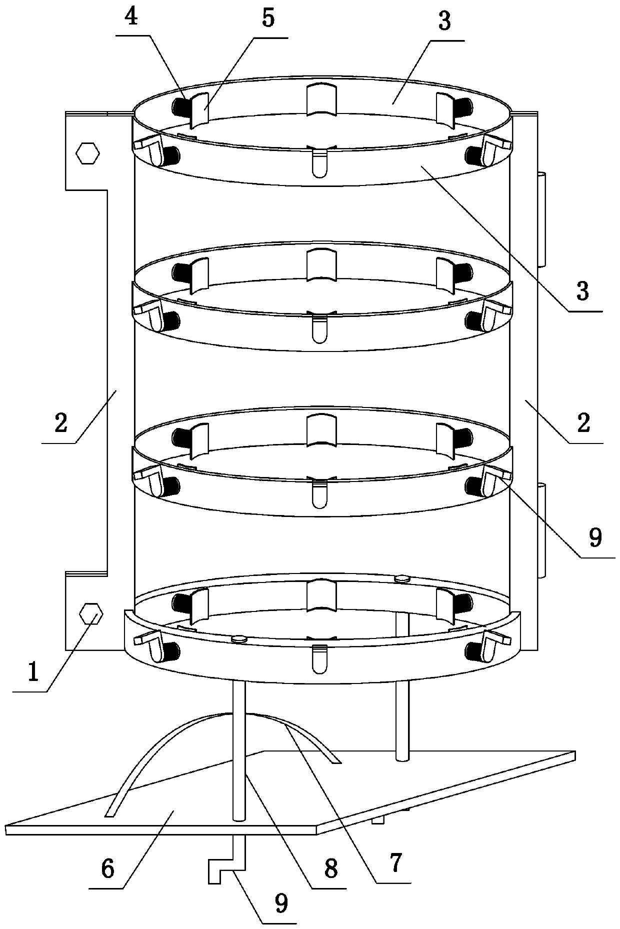
[0031] like figure 1 Shown, the present invention comprises columnar support mechanism and traction mechanism:

[0032] The column support mechanism includes two arc-shaped frames, the right ends of the two arc-shaped frames are connected by hinges, and the left ends are fixed by bolts 1. The arc-shaped frames include two supporting plates 2 and four A first arc-shaped plate 3, the first arc-shaped plate 3 is provided with three first threaded through holes along the circumference, the first threaded through hole is internally threaded to connect the first screw 4, and one end of the first screw 4 is connected to the second arc. Plate 5, the second arc-shaped plate 5 is located in the columnar support mechanism, and the lower end of the columnar support mechanism is provided with two through holes, the first arc-shaped plate 2 and the second arc-shaped plate 5 are made of transparent resin materials;

[0033] The traction mechanism includes a pedal 6 and a cable tie 7 arrange...

Embodiment 2

[0035] The structure of this embodiment is basically the same as that of Embodiment 1, the difference is: as figure 2 As shown, the inner end surface of the second arc-shaped plate 5 is provided with a protective mechanism, and the protective mechanism successively includes a rubber layer 10, an airbag layer 11 and a non-woven fabric layer 12 bonded and fixed, and the rubber layer 10 is fixedly connected with the second arc-shaped plate 5 .

Embodiment 3

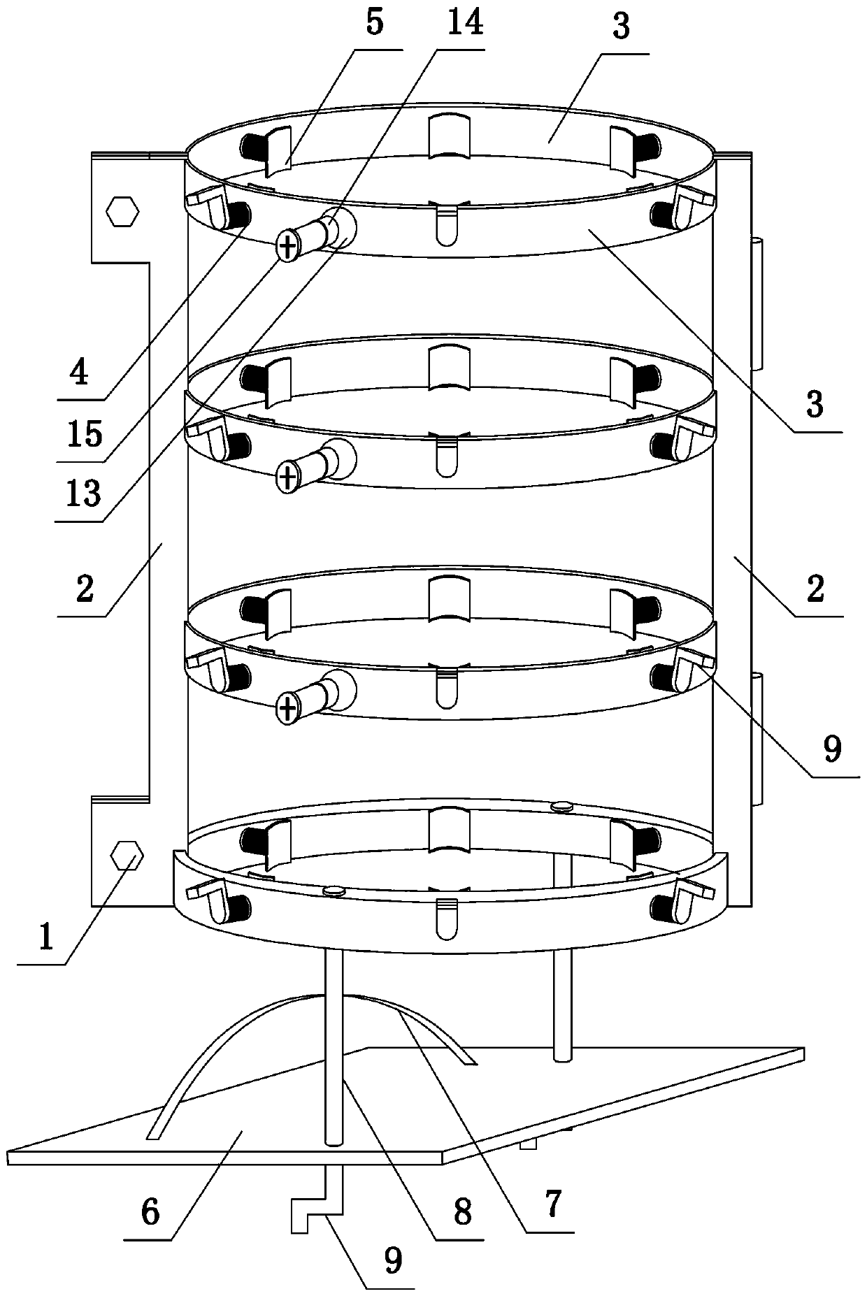
[0037] like image 3 Shown, the present invention comprises column support mechanism, traction mechanism and positioning mechanism:

[0038] The column support mechanism includes two arc-shaped frames, the right ends of the two arc-shaped frames are connected by hinges, and the left ends are fixed by bolts 1. The arc-shaped frames include two support plates 2 and four A first arc-shaped plate 3, the first arc-shaped plate 3 is provided with three first threaded through-holes along the circumference, the first threaded through-holes are internally threaded to connect the first screw 4, and one end of the first screw 4 rotates to connect the second arc-shaped Plate 5, the second arc-shaped plate 5 is located in the columnar support mechanism, and the lower end of the columnar support mechanism is provided with two through holes, and the first arc-shaped plate 2 and the second arc-shaped plate 5 are made of transparent resin materials;

[0039] The traction mechanism includes a pe...


PUM


Abstract

The invention belongs to the technical field of medical equipment for the orthopedics department, and particularly relates to a leg fracture reduction device for the orthopedics department. A columnarsupporting mechanism comprises two arc frames, each arc frame comprises two supporting plates and multiple first arc plates fixed between the two supporting plates, each first arc plate is provided with multiple first threaded through holes, the insides of the first threaded through holes are in threaded connection with first screws, one end of each first screw is rotatably connected with a second arc plate, and two penetrating holes are formed in the lower end of the columnar supporting mechanism; a traction mechanism comprises a pedal and a binding belt, second threaded through holes are formed in the two ends of the pedal respectively, the insides of the second threaded through holes are in threaded connection with second screws, and the ends of the second screws are rotatably connected with the penetrating holes. The upper portion of a fracture part is circumferentially fixed in advance, pulling is conducted through the traction mechanism, finally gradual pushing reduction is conducted, the problem in the prior art that the pulling force cannot be controlled is solved, and the controllability in the treatment process is improved.

Description

technical field [0001] The invention belongs to the technical field of orthopedic medical equipment, in particular to an orthopedic leg fracture reduction device. Background technique [0002] In the treatment of fracture reduction in orthopedic surgery, the current reduction of the fracture site is first required. After the reduction is satisfactory, internal fixation or external fixation is used for fixation. The effect of reduction will directly affect the rehabilitation effect of the patient in the later stage. The commonly used reduction method in China Generally, there are two types: one is open reduction, the operation process of this method is relatively simple and easy to operate, but for patients, there are large trauma, heavy bleeding, easy infection, high requirements on the skin, and easy fracture nonunion after periosteum damage The second is closed reduction, relying on the clinical experience of doctors, and using X-ray fluoroscopy to assist in confirming the...

Claims


Application Information

Patent Timeline
Patent Type & Authority Patents(China)
IPC IPC(8): A61B17/62
CPCA61B17/62A61B2017/564
Inventor 刘念
Owner NANYANG CITY CENT HOSPITAL
Learn More