Movable camera

A camera and mobile technology, applied in the field of mobile cameras, can solve the problems of large impact of event tracking, increased difficulty, and the existence of four corners.

Pending Publication Date: 2018-02-16
河南力方网络科技有限公司
View PDF4 Cites 6 Cited by
  • Summary
  • Abstract
  • Description
  • Claims
  • Application Information

AI Technical Summary

Problems solved by technology

[0002] Due to the frequent occurrence of various adverse events, the requirements for monitoring are becoming more and more stringent. The key to monitoring is the camera. There are more and more types of cameras, and the requirements for cameras are getting higher and higher; the current camera Although it is possible to rotate at a certain angle, sometimes there are still four corners, resulting in the omission of important information, which has

Method used


Image

  • Movable camera
  • Movable camera
  • Movable camera

Examples


Embodiment Construction

[0017] The specific implementation manners of the present invention will be described in detail below in conjunction with the accompanying drawings.

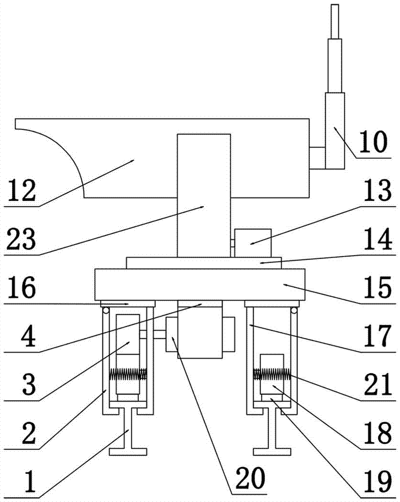
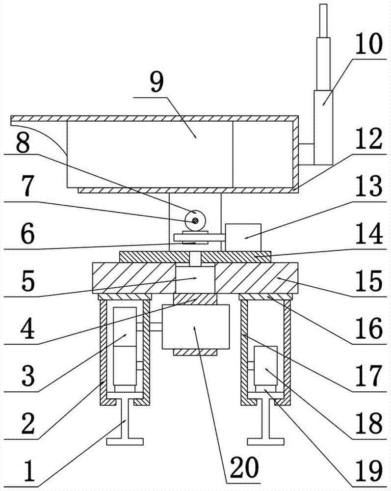
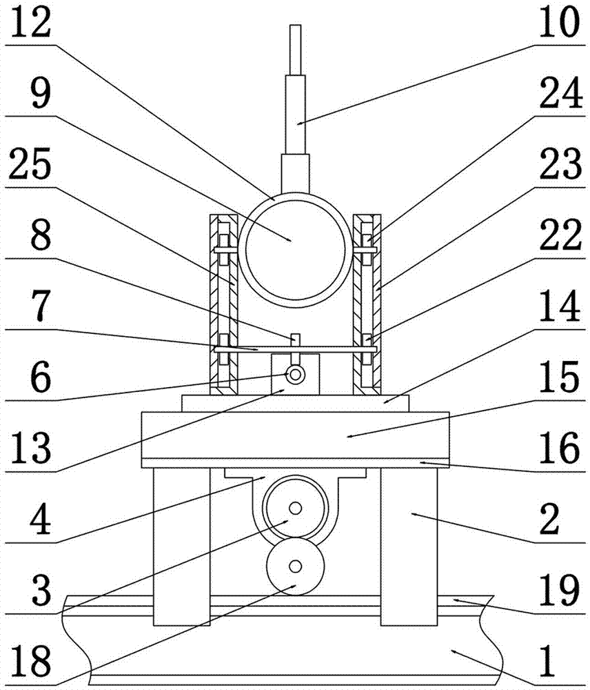
[0018] like Figure 1~Figure 3 As shown, the movable camera includes a camera body 9 and a walking mechanism. The camera body 9 is provided with a camera housing 12 outside, and the camera housing 12 is provided with connecting shafts laterally on both sides. An antenna 10 is arranged at the rear end of the 12; a camera fixing device is arranged at the bottom of the camera housing 12, and a partition 15 is arranged at the bottom of the camera fixing device, and a through hole is reserved in the center of the partition 15, and a rotating shaft is arranged in the through hole. Motor 5, the bottom of the rotating motor 5 is installed on the motor mount 4, and the motor mount 4 is bolted to the partition 15; the partition 15 is made of insulating material; the bottom of the partition 15 is arranged with Traveling mechanism, describ...


PUM


Abstract

The invention discloses a movable camera. The movable camera comprises a camera body and a walking mechanism, a camera shell is arranged on the outer portion of the camera body, connecting shafts aretransversely arranged on the two sides of the camera shell, a camera fixing device is arranged on the lower portion of the camera shell, and a partition plate is arranged on the bottom of the camera fixing device. The walking mechanism is arranged on the lower portion of the partition plate and comprises top plates and guide rails, the top plates are arranged at the two ends of the partition platerespectively, the two ends on the lower portion of each top plate are provided with an outer side plate and a fixing side plate in parallel respectively, walking driving wheels are arranged on the upper side in the outer side plate and the fixing side plate which are located at the same end of the lower portion of the partition plate, walking driven wheels are arranged on the lower portion in theouter side plate and the fixing side plate which are located at the same end of the lower portion of the partition plate, the walking driving wheels penetrate through a fixing seal plate and is rotationally connected with a second motor, and racks are uniformly distributed on the lower portions of the walking driven wheels respectively and arranged on the guide rails in parallel respectively. Bymeans of the movable camera, it is achieved that the camera rotates vertically and horizontally and moves linearly, and the monitoring area is increased.

Description

technical field [0001] The invention relates to the technical field of monitoring, in particular to a movable camera. Background technique [0002] Due to the frequent occurrence of various adverse events, the requirements for monitoring are becoming more and more stringent. The key to monitoring is the camera. There are more and more types of cameras, and the requirements for cameras are getting higher and higher; the current camera Although it is possible to rotate at a certain angle, sometimes there are still four corners, resulting in the omission of important information, which has a great impact on the tracking of some events and increases the difficulty; moreover, most of the cameras are fixed in one place for For monitoring, if some cameras are damaged, it will become a blind spot, which is very inconvenient. Therefore, in order to solve the above problems, it is urgent to design a movable camera, which realizes the rotation of the camera up and down, left and right,...

Claims


Application Information

Patent Timeline
IPC IPC(8): F16M11/04F16M11/08F16M13/02H04N5/225
CPCF16M11/043F16M11/046F16M11/08F16M13/02H04N23/50
Inventor 方俊海
Owner 河南力方网络科技有限公司
Why Eureka
Try Eureka