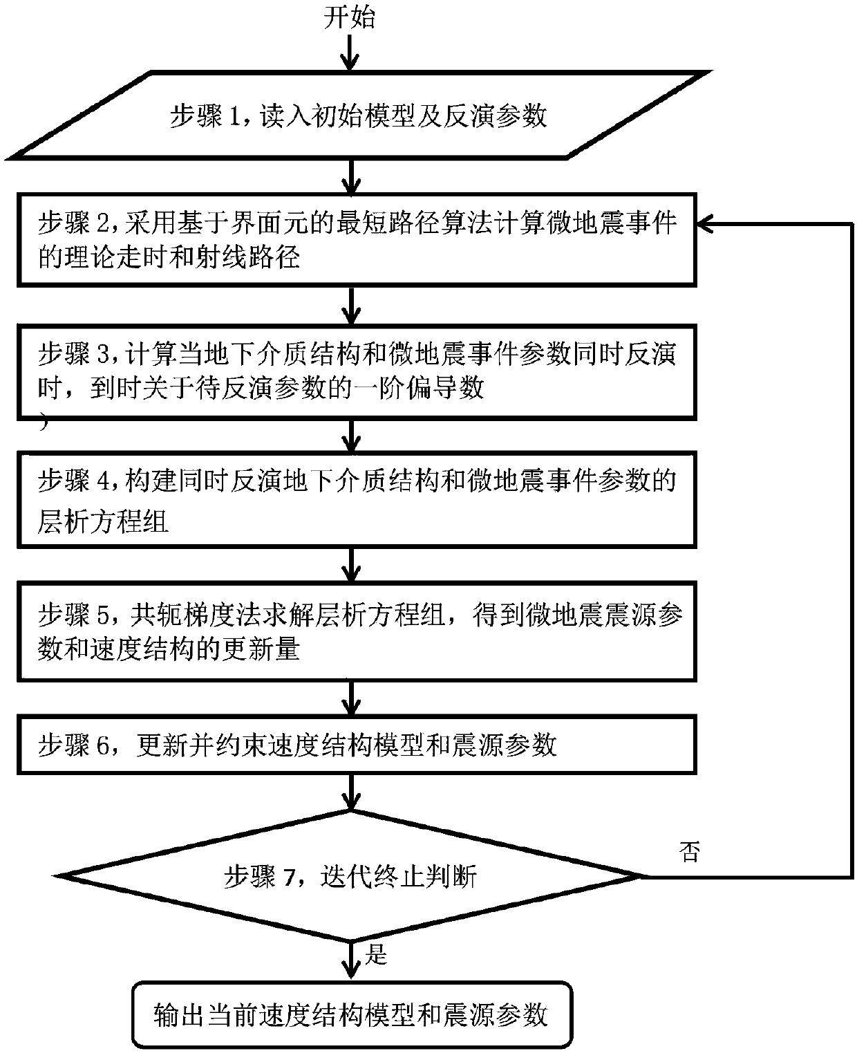
A microseismic positioning and tomographic imaging method
A tomographic imaging and microseismic technology, applied in seismology, seismic signal processing, geophysical measurement, etc., can solve the problems of real result error and time-consuming calculation, and achieve the goal of improving accuracy, reducing number, and reducing dependence Effect
- Summary
- Abstract
- Description
- Claims
- Application Information
AI Technical Summary
Problems solved by technology
Method used
Image
Examples
Embodiment 1
[0083] Embodiment 1 is the calculation example of a kind of microseismic positioning and tomographic imaging method proposed by the present invention, and its specific calculation results are further disclosed as follows:
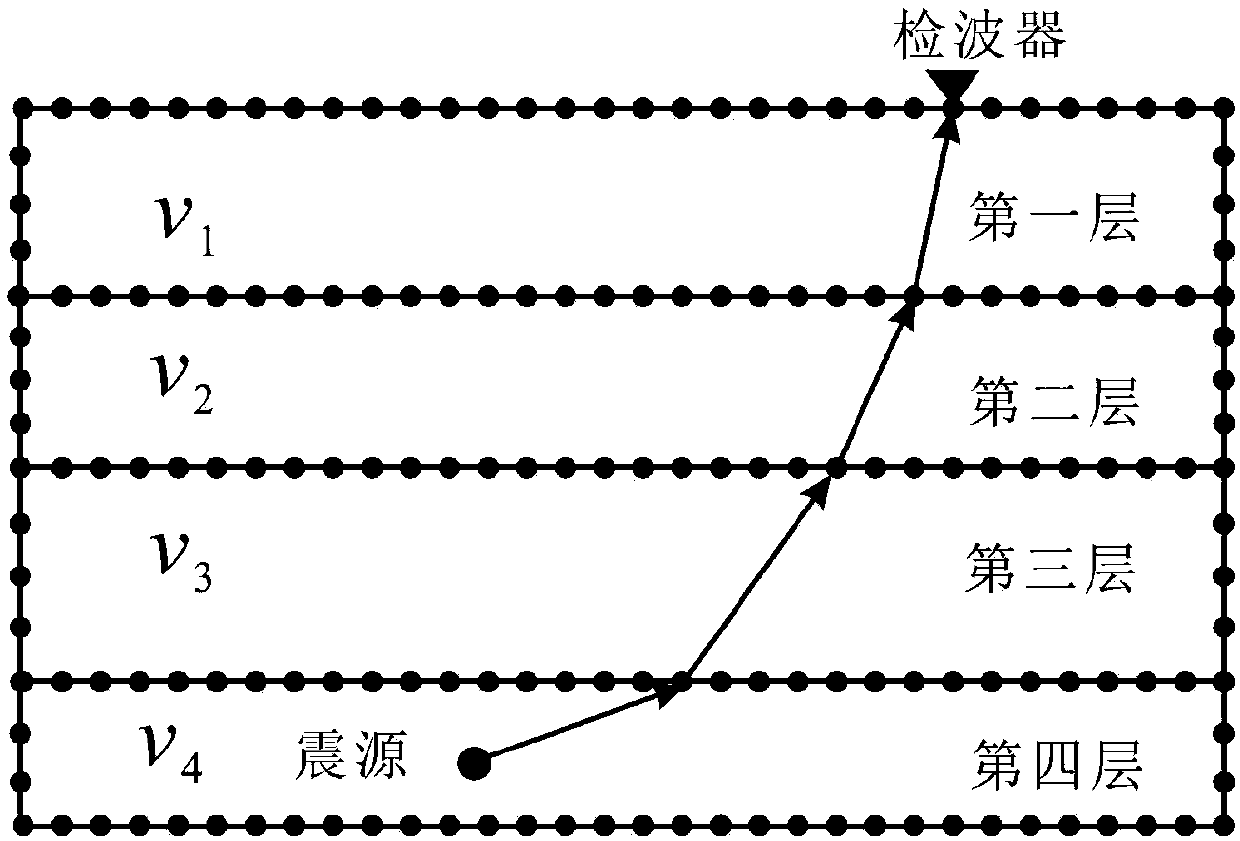
[0084] Such as Figure 4 As shown, the model established for Embodiment 1 of the present invention is a four-layer horizontal layered medium, and the speed is successively 2.0km / s, 2.4km / s, 2.8km / s and 3.2km / s from the surface, and the layer The depths of the interface are 16m, 30m and 40m respectively. The surface “m” type commonly used in microseismic and the joint observation method in the well are adopted (the geophones are arranged as follows Figure 4 shown in the middle triangle). Figure 4 The dots in the middle represent the set four microseismic events, and their spatial coordinates are S1 (20, 40, 42), S2 (100, 100, 45), S3 (150, 180, 48), S4 (170, 30, 26), The excitation times were 10ms, 15ms, 20ms and 5ms, respectively.
[0085] Figure 5 ...
PUM
 Abstract
Description
Claims
Application Information
 - R&D
- Intellectual Property
- Life Sciences
- Materials
- Tech Scout
- Unparalleled Data Quality
- Higher Quality Content
- 60% Fewer Hallucinations
Browse by: Latest US Patents, China's latest patents, Technical Efficacy Thesaurus, Application Domain, Technology Topic, Popular Technical Reports.
© 2025 PatSnap. All rights reserved.Legal|Privacy policy|Modern Slavery Act Transparency Statement|Sitemap|About US| Contact US: help@patsnap.com


