Solid plasma-based wideband variable-frequency antenna

A plasma and solid technology, applied in antennas, devices that make antennas work in different frequency bands at the same time, and the structure of radiating elements, etc., can solve the problems of limited frequency hopping bandwidth of variable frequency antennas

Active Publication Date: 2018-02-16
BEIJING INST OF REMOTE SENSING EQUIP
View PDF3 Cites 0 Cited by
  • Summary
  • Abstract
  • Description
  • Claims
  • Application Information

AI Technical Summary

Problems solved by technology

[0003] The purpose of the present invention is to provide a solid plasma-based broadband frequency conversion antenna

Method used


Image

  • Solid plasma-based wideband variable-frequency antenna

Examples


Embodiment Construction

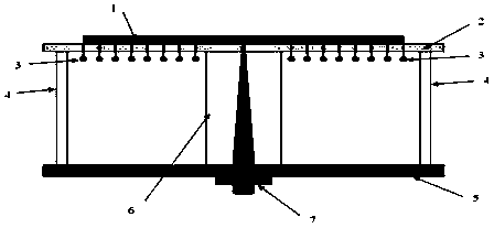
[0013] A broadband variable frequency antenna based on solid plasma, comprising: a broadband balun 6 and a radio frequency joint 7, further comprising: a solid plasma generator array 1, a substrate substrate 2, a bias electrode 3, a pillar 4 and a metal base 5 .

[0014] The solid plasma generator array 1 is composed of multiple rows of solid plasma generators that are closely arranged, and each row is composed of multiple solid plasma generators connected end to end.

[0015] The pillar 4 is a cylindrical shell structure with open upper and lower ends, the substrate substrate 2 is a plate-like structure with a plurality of through holes, and the substrate substrate 2 is covered and fixed on the upper port of the pillar 4; The generator array 1 is installed on the upper surface of the substrate substrate 2, and a plurality of bias electrodes 3 are connected under the solid-state plasma generator array 1, and the plurality of bias electrodes 3 pass through the through holes on ...


PUM


Abstract

The invention discloses a solid plasma-based wideband variable-frequency antenna. The solid plasma-based wideband variable-frequency antenna comprises a solid plasma generator array (1), a substrate (2), biasing electrodes (3), a strut (4), a metal base (5), a wideband Balun (6) and a radio frequency connector (7), wherein the substrate (2) covers an upper port of the strut (4), the solid plasma generator array (1) is arranged on an upper surface of the substrate (2), a plurality of biasing electrodes (3) are connected to a part below the solid plasma generator array (1), the wideband Balun (6) is arranged in a cavity of the strut (4), an upper end of the wideband Balun (6) penetrates through the substrate (2) and is welded on the solid plasma generator array (1), and a lower end of the wideband Balun (6) is welded with the radio frequency connector (7) fixed at a part below the metal base (5). By the method, application in a frequency hopping radar and a frequency hopping communication system can be achieved.

Description

technical field [0001] The invention relates to a frequency conversion antenna, in particular to a wideband frequency conversion antenna based on solid plasma. Background technique [0002] In modern radar, communication and other systems, making full use of frequency hopping signals can reduce the interception rate, enhance the ability of multiple access networking, and anti-jamming capabilities. The frequency conversion antenna is a necessary component for the system to realize the above functions. A variable frequency antenna generally includes a radiator, a feeder, a frequency switch and a radio frequency connector. The radiator is mainly used to generate electromagnetic waves and radiate into space, and the radiator of the variable frequency antenna can radiate electromagnetic waves of different frequencies within a certain frequency band. Since the structure and form of the commonly used metal radiators are relatively determinate, that is, they have determinate frequ...

Claims


Application Information

Patent Timeline
IPC IPC(8): H01Q1/38H01Q5/10H01Q5/20
CPCH01Q1/38H01Q5/10H01Q5/20
Inventor 董胜波刘涓杨岱旭
Owner BEIJING INST OF REMOTE SENSING EQUIP
Why Eureka
Try Eureka