A Broadband Pattern Reconfigurable Antenna

A technology for reconstructing antennas and directional diagrams, applied to antennas, radiating element structures, electrical components, etc., can solve problems such as system cost, weight, and volume increase, and achieve the effects of light weight, good directivity, and widened impedance bandwidth

Inactive Publication Date: 2018-01-16
SOUTH CHINA UNIV OF TECH
View PDF5 Cites 0 Cited by
  • Summary
  • Abstract
  • Description
  • Claims
  • Application Information

AI Technical Summary

Problems solved by technology

At present, the important direction of wireless communication system development is large capacity, multi-function, and ultra-wideband. In order to meet this demand, the number of antennas mounted on the same platform will increase accordingly, and the increase in the number of antennas will inevitably lead to an increase in system cost, weight, and volume. , but also brings about the problem of electromagnetic compatibility

Method used


Image

  • A Broadband Pattern Reconfigurable Antenna
  • A Broadband Pattern Reconfigurable Antenna
  • A Broadband Pattern Reconfigurable Antenna

Examples


Embodiment

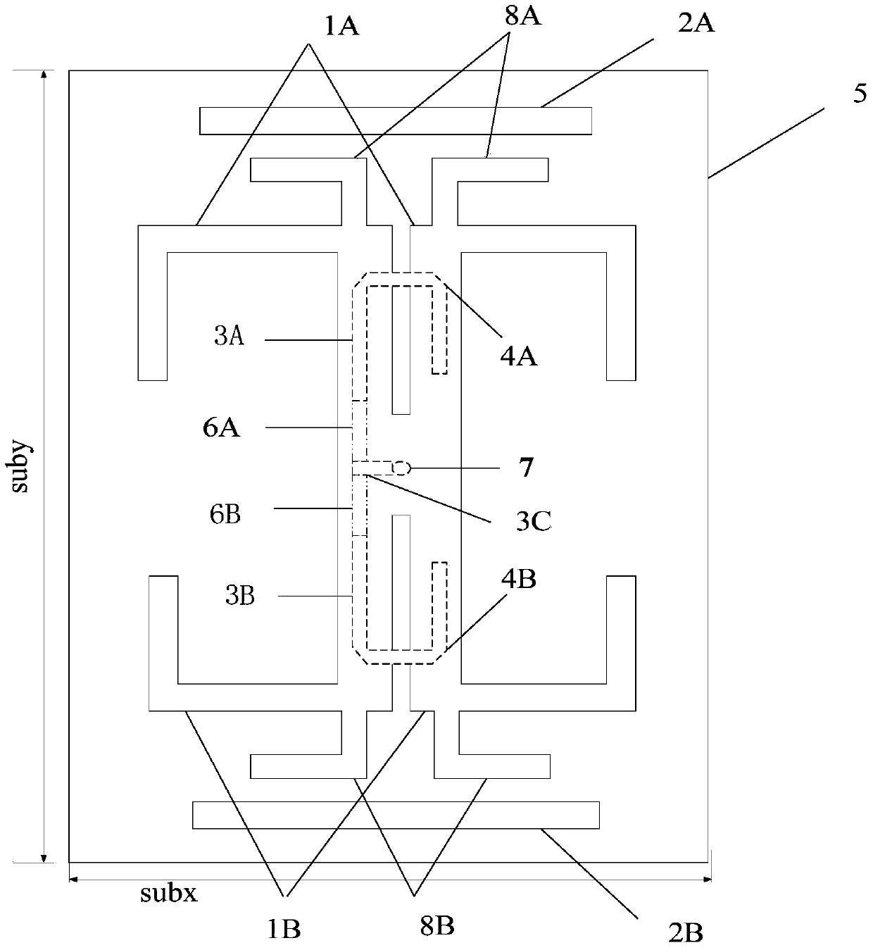
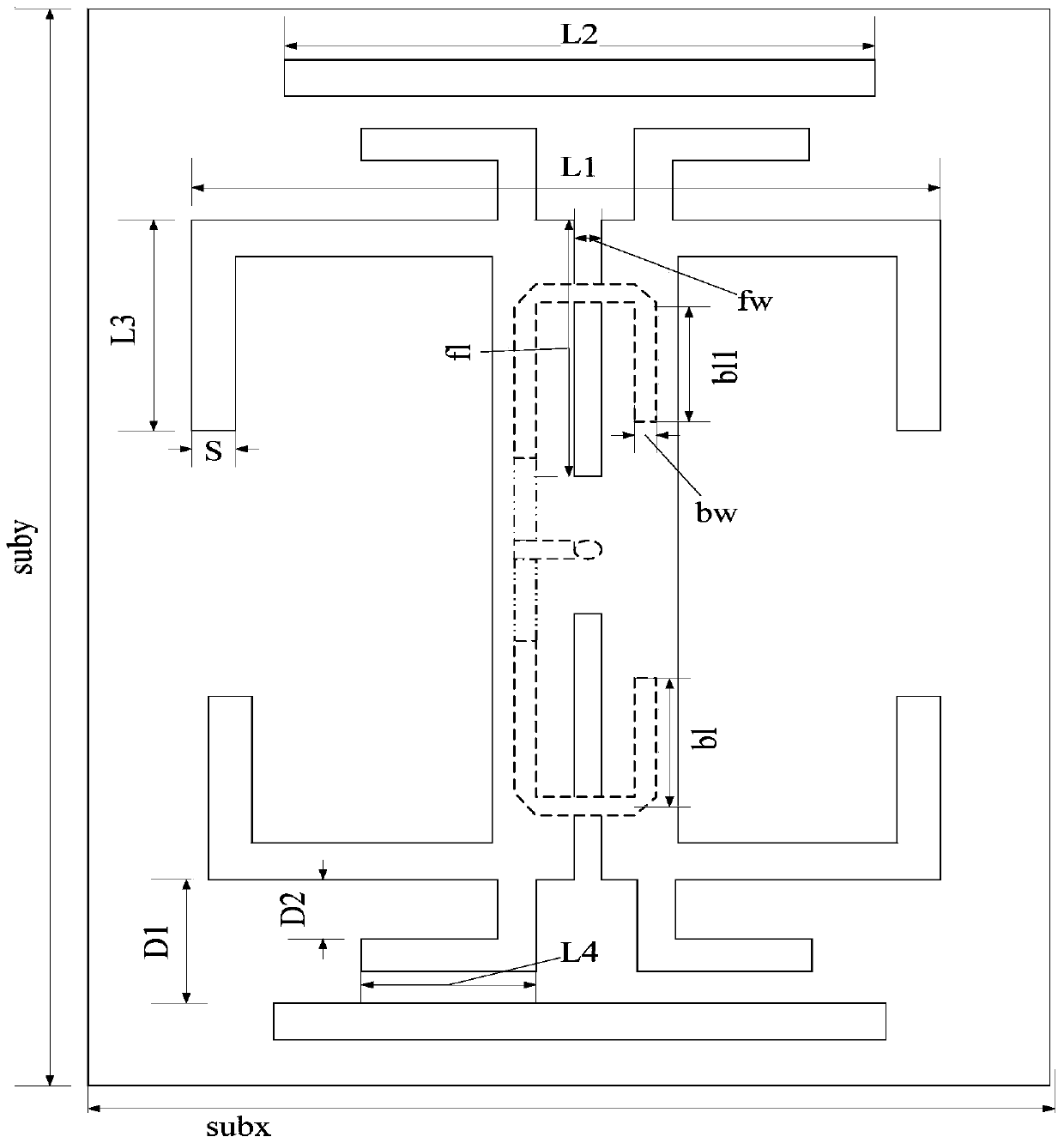
[0036] Such as Figures 1 to 11 shown. A broadband pattern reconfigurable antenna according to the present invention includes a substrate 5 and a broadband coupling feed balun. The front side of the substrate 5 is etched with two parallel and mutually spaced main radiation units of the antenna. The substrate 5 The back is etched with a broadband coupling feed balun; the ends of the two parallel and mutually spaced main radiation units are respectively provided with a pair of "L"-shaped bent dipole radiation units 1A and 1B; the two parallel and mutually spaced There are slot lines between the dipole arms of the spaced main radiating elements. The specific dimensions of the groove line between the dipole arms of the two parallel and mutually spaced main radiation units are as follows: the length of the groove is 18mm, and the width of the groove is about 1.5mm.

[0037] A pair of straight dipole units 8A, 8B are respectively provided at the ends of the two parallel and mutual...


PUM


Abstract

The invention discloses a broadband pattern reconfigurable antenna, which comprises a substrate and a broadband coupling feed balun, two parallel and mutually spaced main radiation units of the antenna are etched on the front side of the substrate, and the back side of the substrate Etch broadband coupling feed balun; the ends of the two parallel and spaced main radiation units are each provided with a pair of "L"-shaped bent dipole radiation units; the two parallel and spaced main radiation units A pair of straight dipole units are respectively provided at the ends of the units. The broadband pattern reconfigurable antenna has the advantages of small size, light weight, simple structure, no reflector, wide bandwidth, and can realize the reconfigurable pattern of E plane and H plane at the same time, which is suitable for military and civilian radar, wireless communication, Advantages in the field of intelligent weapon guidance.

Description

technical field [0001] The invention relates to the technical field of antennas, in particular to a reconfigurable antenna with a broadband pattern. Background technique [0002] In recent years, wireless communication technology has developed rapidly, and antenna, as a component used to transmit or receive radio waves, plays a pivotal role in wireless communication systems. At present, the important direction of wireless communication system development is large capacity, multi-function, and ultra-wideband. In order to meet this demand, the number of antennas mounted on the same platform will increase accordingly, and the increase in the number of antennas will inevitably lead to an increase in system cost, weight, and volume. , but also brought about electromagnetic compatibility issues. In order to overcome this constraint and make the performance of the entire communication system less constrained by the antenna, reconfigurable antennas emerge as the times require. [...

Claims


Application Information

Patent Timeline
Patent Type & Authority Patents(China)
IPC IPC(8): H01Q25/00H01Q1/36
Inventor 李融林杨欢孙成煊
Owner SOUTH CHINA UNIV OF TECH
Why Eureka
Try Eureka