Electric tool
A technology for electrical appliances and power supply, which can be used in electrical alarms, alarms that rely on moving hand-held items, mechanical activation of anti-theft alarms, etc., and can solve problems such as easy theft
- Summary
- Abstract
- Description
- Claims
- Application Information
AI Technical Summary
Problems solved by technology
Method used
Image
Examples
Embodiment approach 1
[0032] One embodiment of the present invention will be described.
[0033] (1-1. Overall configuration of ion generator 100)
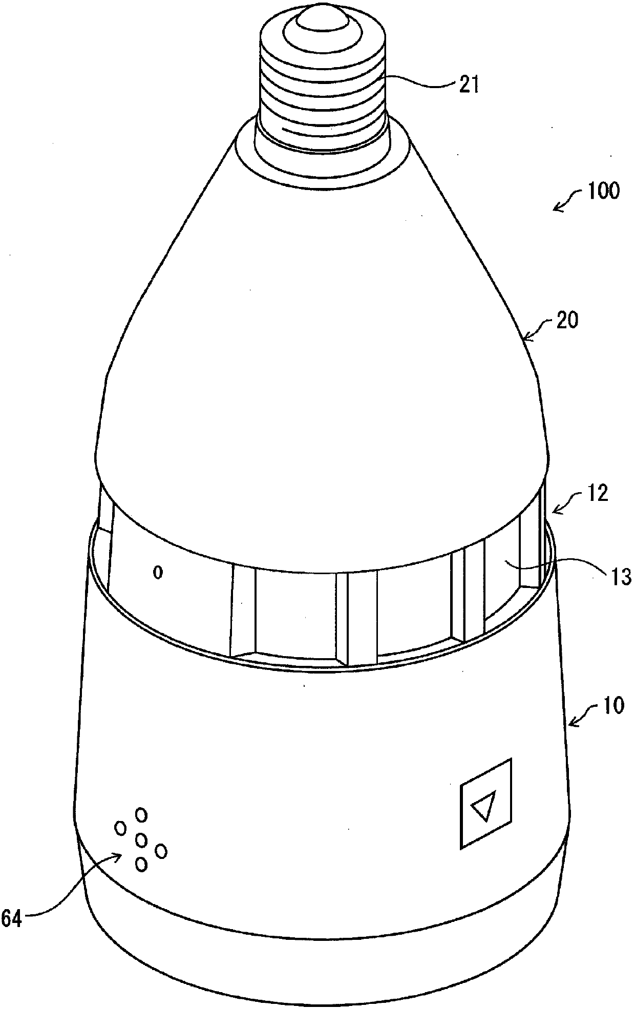
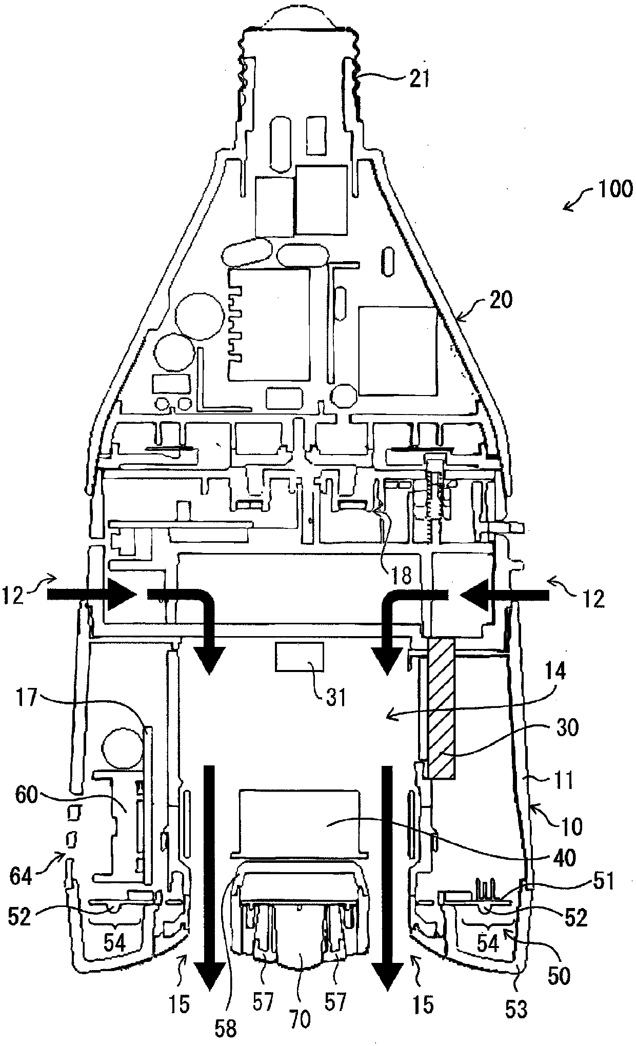
[0034] figure 1 It is a perspective view of the ion generator (electric appliance) 100 of this embodiment, figure 2 is a cross-sectional view of the ion generator 100 .
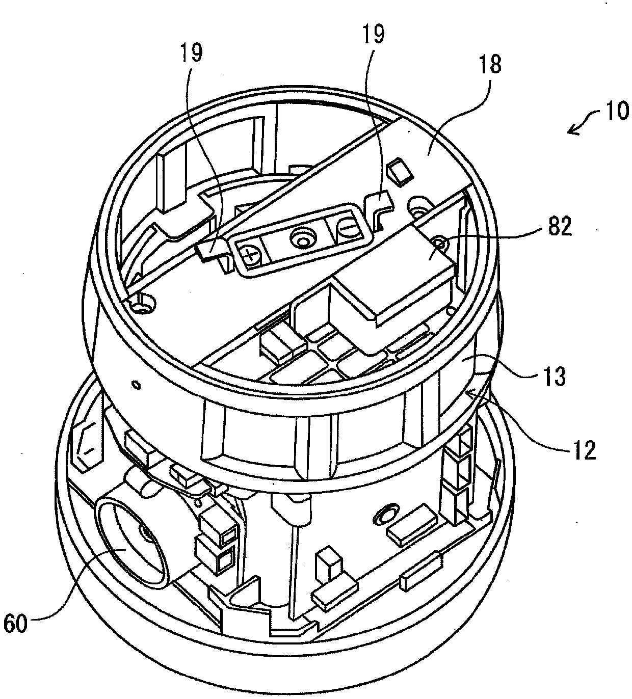
[0035] Such as figure 1 and figure 2 As shown, the ion generator 100 is equipped with the adapter 20, and the main-body part 10 attached to the adapter 20 so that attachment and detachment are possible.
[0036] The adapter (attachment unit) 20 includes a plug (base plug) 21 to be attached to a socket (attachment site) installed on a ceiling, wall, floor, installation surface of various appliances, and the like. That is, a helical thread and a helical groove are formed at positions corresponding to each other in the plug 21 and the socket, and the ion generator 100 is attached to and detached from the socket by rotating the ion generator 100 .
[0037] And by attaching the plu...
Embodiment approach 2
[0104] Another embodiment of the present invention will be described. In addition, for convenience of explanation, the same symbols are attached to components having the same functions as those in Embodiment 1, and description thereof will be omitted.
[0105] In Embodiment 1, the configuration for performing the warning operation when the power supply to the main body unit 10 is interrupted has been described. On the other hand, in the present embodiment, a description will be given of a configuration in which a warning operation is performed when the main body portion 10 is rotated or moved.
[0106] Figure 8 It is a block diagram which shows the structure of the control system and the power supply system in the ion generator 100 of this embodiment.
[0107] Such as Figure 8 As shown, the ion generator 100 of this embodiment replaces Figure 5 The voltage detection part 81 in the ion generator 100 shown has the rotation detection part 86. As shown in FIG.
[0108] The...
Embodiment approach 3
[0117] Still another embodiment of the present invention will be described. In addition, for convenience of description, the same reference numerals are attached to components having the same functions as those in the above-mentioned embodiment, and description thereof will be omitted.
[0118] In Embodiment 1, the description has been given of the configuration in which the warning operation is performed when the power voltage to the main body 10 has dropped below a predetermined value. On the other hand, in the present embodiment, a description will be given of a configuration in which a warning operation is performed when the detection results of the human detection sensor 70 and the detection results of the supply voltage to the main body 10 satisfy predetermined conditions.
[0119] Figure 10 It is a block diagram which shows the structure of the control system and the power supply system in the ion generator 100 of this embodiment. As shown in this figure, in the ion ...
PUM
 Abstract
Description
Claims
Application Information
 - R&D
- Intellectual Property
- Life Sciences
- Materials
- Tech Scout
- Unparalleled Data Quality
- Higher Quality Content
- 60% Fewer Hallucinations
Browse by: Latest US Patents, China's latest patents, Technical Efficacy Thesaurus, Application Domain, Technology Topic, Popular Technical Reports.
© 2025 PatSnap. All rights reserved.Legal|Privacy policy|Modern Slavery Act Transparency Statement|Sitemap|About US| Contact US: help@patsnap.com


